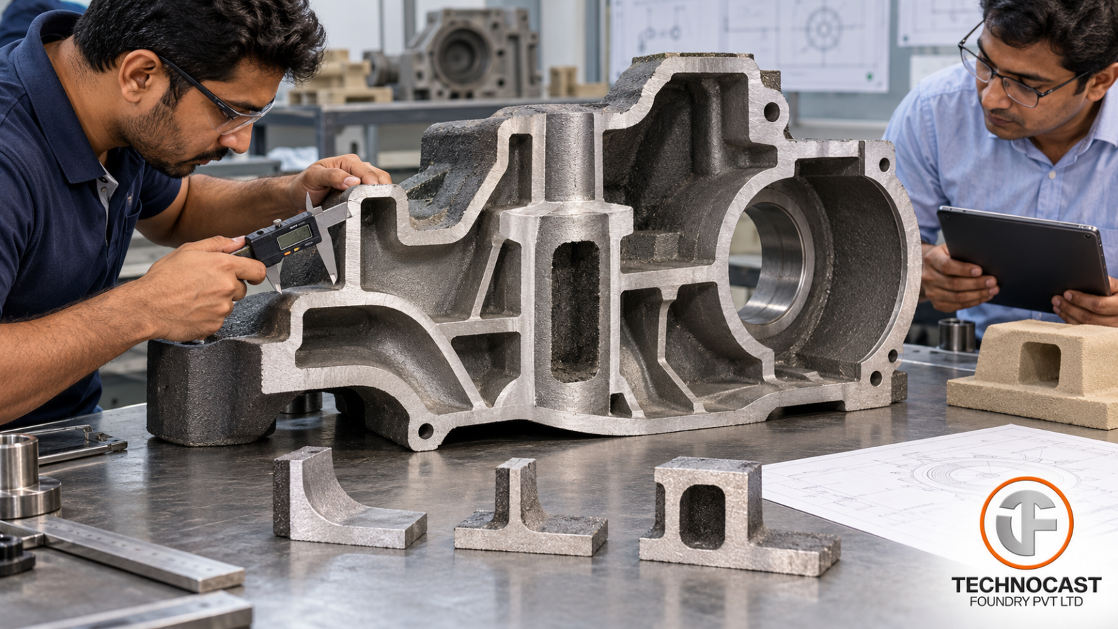
A casting drawing should describe more than the final shape of the component.
It should provide a realistic manufacturing route from:
Pattern → Mould → Pouring → Solidification → Shakeout → Machining → Inspection
A wall may be structurally strong enough in CAD and still be difficult to manufacture if:
- Metal cannot fill the section reliably
- A heavy junction becomes difficult to feed
- The pattern cannot be withdrawn cleanly
- A core cannot be supported reliably
- Machining stock disappears after distortion
- Several ribs create a concentrated hot spot
For OEM and Tier supplier engineers, the useful design question is therefore not simply:
“Is this wall thick enough?”
It is:
“Can the foundry fill it, feed it, form it, release it, inspect it and machine the critical surfaces repeatedly?”
That is the basis of good casting DFM.
Start With the Casting Model, Not Only the Finished Component
A finished CAD model often represents geometry after machining.
The foundry, however, needs to manufacture the geometry that exists before machining.
Those two models should not be treated as identical.
During DFM, review:
- Finished-component geometry
- Raw-casting geometry
- Machining stock
- Parting line
- Pattern pull direction
- Core requirements
- Gating and feeding strategy
- Critical inspection locations
before tooling is frozen.
Separate Functional Regions
Different areas of the component often need different treatment.
Consider an engine or gearbox housing.
The design may contain:
- Structural shell
- Bearing bosses
- Mounting pads
- Seal interfaces
- Internal cavities
- Rib networks
A pump casing may contain:
- Pressure boundary
- Volute geometry
- Flange stock
- Mounting feet
A suspension bracket may contain:
- Fatigue-critical fillets
- Bored interfaces
- Load-transfer bosses
These regions should be reviewed individually rather than approving the casting from one nominal wall-thickness value.
Why Wall Thickness Matters in Sand Casting
Wall thickness affects several manufacturing behaviours simultaneously.
It influences:
- Metal flow
- Filling
- Cooling rate
- Solidification
- Feeding
- Microstructure
- Distortion
- Casting weight
- Cycle time
A section can therefore be too thin for reliable filling or too heavy for predictable solidification.
Good casting design aims for sections that are:
fill-able + feedable + structurally appropriate.
There Is No Universal Minimum Wall Thickness
One of the most dangerous shortcuts in casting design is asking:
“What is the minimum sand-casting wall thickness?”
and expecting one number.
The answer depends on:
- Material
- Moulding process
- Casting size
- Flow length
- Pouring temperature
- Geometry
- Core configuration
- Production conditions
The supplied design reference cites approximately 5 mm for certain ductile-iron sections up to 300 mm in length as a handbook recommendation.
That should be treated only as a conditional design starting point.
It is not a universal rule that every ductile-iron casting can safely use 5 mm walls.
The actual feature should be reviewed with the foundry.
Thin Walls Need More Than Thickness Review
A thin wall near the gate can behave differently from an identical wall at the end of a long flow path.
When reviewing thin regions, consider:
- Distance metal must travel
- Number of direction changes
- Adjacent heavy sections
- Local heat loss
- Core surface area
Therefore:
5 mm at one location is not automatically equivalent to 5 mm somewhere else.
Build a Wall-Thickness Map
One useful DFM exercise is creating a wall-thickness map of the component.
Identify:
Minimum sections
Where filling may be difficult.
Maximum sections
Where solidification may be slow.
Long flow paths
Where metal must travel through relatively thin geometry.
Heavy nodes
Where several walls, ribs or bosses converge.
Abrupt transitions
Where one section suddenly becomes much thicker than another.
This usually provides more useful engineering information than simply calculating the average wall thickness.
Keep Wall Thickness as Uniform as Practical
Uniform sections generally solidify more predictably than abrupt combinations of thin and heavy metal.
This does not mean every wall must have identical thickness.
Functional design frequently requires variation.
The objective is to avoid unnecessary sudden changes.
Instead of:
Thin wall → Large solid block
prefer:
Thin wall → Gradual transition → Required heavy section
where structure and manufacturability allow it.
Why Heavy Sections Create Risk
Thicker sections cool more slowly than neighbouring thin sections.
This can create concentrated thermal mass.
Potential consequences include:
- Shrinkage
- Porosity
- Microstructural variation
- Residual stress
- Longer solidification time
A component should therefore be reviewed for metal concentration, not just obvious wall thickness.
Several individually acceptable walls can still create a heavy junction when they meet.
Think in Terms of Thermal Modulus
A region containing a large volume of metal relative to its cooling surface tends to remain hot longer.
That makes it more difficult to solidify and feed than surrounding thin sections.
For DFM purposes, engineers should therefore look for:
- Large bosses
- Thick flange junctions
- Rib intersections
- Bearing pedestals
- Multiple-wall intersections
rather than checking isolated dimensions only.
Gearbox Housing Example
Imagine a gearbox housing with:
- 7 mm shell
- Large bearing pedestal
Connecting the shell directly into a completely solid pedestal may produce a substantial local hot spot.
Alternative concepts could include:
- Hollowing the pedestal
- Introducing a more gradual transition
- Modifying rib geometry
- Improving feeding access
The final option must still satisfy structural and machining requirements.
The objective is not simply reducing metal.
It is balancing:
Load path + Casting behaviour + Machining requirement.
Design Smooth Section Transitions
Sudden steps in wall thickness should be reviewed carefully.
Potential high-risk locations include:
- Shell-to-flange transitions
- Boss roots
- Mounting pads
- Bearing supports
- Rib junctions
Use gradual transitions where possible.
A smoother transition can help reduce:
- Thermal concentration
- Abrupt stiffness change
- Stress concentration
while improving casting manufacturability.
Draft Must Be Designed In
Draft is the taper that allows a pattern to be withdrawn from moulding sand without damaging the mould cavity.
It should not be treated as something the tooling supplier adds after the design is complete.
The engineering team should define:
Pattern pull direction first.
Then identify which surfaces require draft.
Typical locations include:
- Exterior vertical walls
- Bosses
- Ribs
- Pockets
- Internal pattern surfaces
Draft Depends on the Feature
There is no single draft angle appropriate for every surface.
Draft requirements can vary according to:
- Feature depth
- Pattern material
- Moulding route
- Surface condition
- Pull direction
- Required dimensional accuracy
A shallow external wall may require a different approach from a deep pocket.
Ask the foundry to review difficult features individually.
Define Where the Controlling Dimension Applies
Draft changes dimensions along the depth of the feature.
Therefore, the drawing should make clear whether the controlling dimension applies at:
- Opening
- Base
- Datum plane
- Machined surface
- Another functional location
Otherwise, tooling and design teams may interpret the same nominal size differently.
Draft Can Affect Machining Stock
Consider a boss that will later be machined.
If draft tapers the boss excessively toward one end, available stock may become insufficient.
That means draft and machining allowance should be reviewed together.
The correct sequence is:
Pattern pull → Draft → Casting variation → Machining stock → Final dimension
rather than treating these as independent decisions.
Fillets Are Manufacturing Features, Not Decoration
Sharp internal corners should generally be avoided in conventional casting design.
Fillets can improve:
- Metal flow
- Stress distribution
- Pattern manufacture
- Mould integrity
However, simply applying very large fillets everywhere is also not good design.
An oversized fillet may create an unintended heavy section.
The correct radius needs to balance:
Structural requirement + Casting geometry + Local thermal behaviour.
Review Junctions in Cross-Section
Many casting problems originate where simple features intersect.
The drawing may look reasonable in an external view but reveal significant metal concentration when sectioned.
Three useful areas to inspect are:
- L junctions
- T junctions
- X junctions
L Junctions
An L-junction occurs where two walls meet at a corner.
Compare:
- Inside radius
- Outside geometry
- Resulting local thickness
A very large internal fillet combined with an unchanged outside corner can produce a heavy mass.
The objective should be a balanced transition.
T Junctions
A T-junction commonly occurs where a rib joins a wall.
Review:
- Rib root
- Wall thickness
- Opposite surface
- Fillet
A thick rib combined with a large root radius can create a local hot spot even if the wall and rib individually appear reasonable.
Where the structural design allows it, consider:
- Reduced rib thickness
- Alternative attachment
- Local relief
X Junctions
When several ribs or webs intersect at one point, the intersection can become much heavier than surrounding sections.
Instead of converging every rib at the same location, consider whether some intersections can be offset or staggered.
Structural analysis should confirm whether the revised arrangement still transfers load correctly.
Ribs Should Add Stiffness Efficiently
Increasing an entire wall thickness is not always the best way to improve stiffness.
Ribs can often provide better structural efficiency.
Good rib design generally considers:
- Load direction
- Rib height
- Rib thickness
- Termination
- Junction geometry
Ribs should follow actual structural requirements rather than being added decoratively.
Avoid Unnecessary Rib Convergence
Multiple ribs terminating in the same boss or pad can create concentrated metal volume.
When reviewing rib layout, ask:
Do all these ribs really need to meet here?
Possible alternatives include:
- Staggering terminations
- Reducing thickness
- Hollowing the central pad
- Changing load path
provided the structural analysis supports the change.
Taper Rib Terminations
Abrupt rib endings can create local stiffness changes and metal concentrations.
Gradual rib termination can improve:
- Load transfer
- Structural transition
- Castability
The exact geometry should still be reviewed for the selected moulding process.
Use Cores Deliberately
Cores allow internal geometry and hollow sections to be produced.
They are particularly useful when a thick solid region can be replaced by a functional cavity.
Potential advantages include:
- Reduced casting weight
- Reduced thermal mass
- Lower material usage
- Reduced shrinkage risk
But cores add another manufacturing system that must be controlled.
Core Design Must Consider Support
A core needs to remain in the intended position during mould assembly and pouring.
DFM should therefore review:
- Core prints
- Support
- Assembly sequence
- Buoyancy
- Movement risk
Core shift may change wall thickness even when the external casting remains dimensionally correct.
Ask the Worst-Case Wall Question
For a cored component, do not only ask:
“What is the nominal wall thickness?”
Ask:
“Which wall becomes thinnest if the core moves to its allowed limit?”
That location may become the actual design constraint.
Core Venting Matters
Gas generated around the core must be able to escape.
Core and mould design should therefore consider:
- Venting
- Binder behaviour
- Gas path
- Pouring conditions
This is another reason internal cavities should be reviewed with the foundry rather than simply modelled geometrically.
Core Removal Must Also Be Considered
An internal cavity is useful only if the core material can be removed after casting.
Deep pockets or enclosed passages may create cleaning difficulties.
The design review should consider:
- Shakeout
- Access
- Cleaning
- Inspection
before tooling is approved.
Machineability Should Influence Casting Geometry
A casting may be perfectly castable but unnecessarily difficult to machine.
DFM therefore needs to consider:
- Tool access
- Fixture location
- Datum surfaces
- Machining allowance
- Clamp locations
before the raw casting design is frozen.
Plan Machining Stock With Wall Thickness
Suppose a structural wall is nominally 8 mm but one side requires 3 mm of machining stock.
The raw casting may therefore need significantly more material locally.
That can change:
- Local cooling
- Solidification
- Feeding
The machining allowance itself becomes part of casting geometry.
It should be included in thermal and DFM review.
As-Cast Wall vs Finished Wall
Drawings should distinguish between:
Raw casting wall thickness
and:
Minimum wall remaining after machining.
This becomes particularly important around:
- Sealing surfaces
- Bores
- Pressure boundaries
- Structural mounting interfaces
A part can have adequate raw thickness yet become too thin after machining if core position or machining location shifts.
Do Not Solve Porosity Automatically by Making the Part Thicker
When porosity is discovered, a common reaction is:
“Add more material.”
That can sometimes make the problem worse.
More metal can:
- Increase thermal mass
- Create a larger hot spot
- Make feeding more difficult
A porosity investigation should first identify the mechanism.
Useful information includes:
- Exact defect location
- Photographs
- Machining depth
- Inspection method
- Heat/lot identification
- Defect distribution
Then review:
- Feeding
- Solidification
- Gating
- Section geometry
before changing wall thickness.
Casting Simulation Should Support Engineering Decisions
Simulation can be valuable before tooling when it is used to answer specific manufacturing questions.
A useful review should identify:
- Filling risk
- Hot spots
- Potential shrinkage
- Feeding behaviour
- Proposed geometry changes
The software name itself is not the evidence.
The source notes Technocast’s published pre-tooling workflow refers to AutoCAST.
For an OEM review, the important output should be:
Inputs → Identified risk → Proposed design change → Trial-validation plan
rather than simply stating:
“Simulation completed.”
Compare Alternatives, Not Just One Simulation
Simulation becomes particularly useful when comparing designs.
For example:
Concept A
Solid bearing pedestal.
Concept B
Hollow pedestal with revised ribs.
Compare them for:
- Filling
- Solidification
- Feeding
- Structural requirements
Then document why the selected geometry was released.
Initial Castings Must Still Validate the Model
Simulation does not replace physical validation.
Early castings should confirm relevant:
- Dimensions
- Wall thickness
- Internal soundness
- Machining stock
- Metallurgical requirements
according to the component’s quality plan.
Wall Thickness Inspection
Depending on the geometry, wall thickness may be checked using:
- Direct measurement
- Fixtures
- Sectioned development samples
- Ultrasonic thickness measurement where suitable
- Other validated methods
The inspection method should be established before production where minimum wall is critical.
DFM Release Checklist
Before releasing a sand-casting design, confirm:
Material
Exact grade agreed.
Moulding Process
Proposed route agreed with the foundry.
Parting Line
Reviewed.
Pull Direction
Defined.
Wall Thickness
Critical thin and heavy regions identified.
Section Transitions
Reviewed for unnecessary abrupt changes.
Draft
Applied feature by feature.
Fillets
Reviewed structurally and thermally.
Junctions
L, T and X intersections examined in section.
Cores
Reviewed for:
- Support
- Position
- Venting
- Removal
Ribs
Aligned to structural requirements without unnecessary metal concentration.
Machining Stock
Included in the casting model.
Datums
Machining and inspection location considered.
Simulation
Any relevant findings translated into engineering decisions.
Inspection
Critical wall and dimensional checks defined.
Technocast DFM Approach
For suitable programs, Technocast can review the casting as a manufacturing system rather than only as a finished CAD shape.
The discussion can connect:
Material → Moulding route → Pattern/tooling → Section design → Core strategy → Machining → Inspection
before tooling is committed.
The supplied material also identifies AutoCAST within Technocast’s pre-tooling simulation workflow.
For each project, the useful objective is to turn the analysis into practical decisions around:
- Section geometry
- Gating/feeding
- Machining stock
- Tooling
- Initial validation
rather than treating simulation as a standalone deliverable.
For any expanded scope involving assembly, confirm the exact current Technocast capability for the specific program before including it contractually.
What to Send for a Casting DFM Review
Provide:
- Finished-component 3D model
- Casting drawing where available
- Material grade
- Single-piece weight
- Annual volume
- Service/load information
- Machined surfaces
- Critical wall locations
- Inspection requirements
This allows the foundry to assess manufacturability before tooling is released.
Conclusion
Good sand-casting design is not about selecting one “safe” wall thickness and applying it everywhere.
A manufacturable casting balances:
Filling + Solidification + Feeding + Pattern withdrawal + Core stability + Structural loading + Machining
The strongest designs typically:
- Avoid unnecessary abrupt section changes
- Manage heavy junctions
- Use draft intentionally
- Balance fillets
- Use ribs efficiently
- Core out unnecessary mass where practical
- Protect machining stock
- Translate simulation findings into geometry decisions
The most important mindset shift is simple:
Do not design only the finished component.
Design the manufacturing route that creates the finished component.
That is what turns an attractive CAD model into a repeatable production casting.
Frequently Asked Questions
What is the minimum wall thickness for sand casting?
There is no universal minimum. It depends on material, casting process, component size, flow length and geometry. Minimum sections should be reviewed with the selected foundry.
Is 5 mm a safe minimum for ductile iron castings?
Not universally. A 5 mm value appears in some design guidance for specific section lengths and conditions, but it should be treated as a starting reference rather than a guaranteed capability.
Why should wall thickness be kept relatively uniform?
Large changes in section thickness create different cooling and solidification rates, potentially increasing shrinkage, porosity, residual stress and microstructural variation.
Why are large fillets sometimes a problem?
Although fillets remove sharp corners, oversized fillets can create concentrated metal mass and slow-cooling regions.
Should ribs be thicker than the wall?
Not automatically. Rib dimensions should follow stiffness and load-transfer requirements while avoiding unnecessary metal concentration at the rib root.
Why are cores used in thick casting sections?
Cores can create hollow geometry, reducing weight and thermal mass while potentially lowering solidification-related risk.
What is core shift?
Core shift occurs when a core moves from its intended position, changing internal geometry and creating uneven wall thickness.
Should machining stock be included during casting DFM?
Yes. Machining allowance changes the raw casting geometry and can affect section thickness, solidification and feeding behaviour.
Can casting simulation guarantee a defect-free casting?
No. Simulation supports engineering decisions, but initial castings still need physical validation according to the agreed quality plan.
Related at Technocast: DISA high pressure moulding line · ARPA 450 and ARPA 1300 moulding lines
Read next: Sand casting tolerances and machining allowances · Casting vs CNC machining