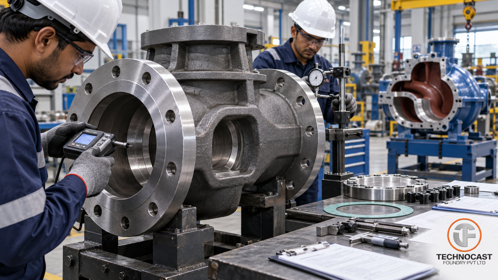
A pump or valve casting is not simply a shaped piece of metal.
It forms part of the pressure boundary.
That changes how the component should be specified, manufactured and inspected.
A specification that simply says:
“Ductile iron valve body”
or:
“WCB pump casing”
leaves too many unanswered questions.
What pressure and temperature must the component withstand?
What fluid will it contain?
Which flange standard applies?
Which surfaces must be machined?
What surface finish is required at the gasket interface?
Is hydrostatic testing mandatory?
Which casting zones require NDT?
Is weld repair permitted?
When these requirements are unclear, problems often appear later as:
- Leakage
- Premature corrosion
- Machining rework
- Gasket failure
- Dimensional mismatch
- Pressure-test rejection
- Field failure
For engineering and procurement teams, a good pump or valve casting specification should function as a measurable manufacturing contract.
It should define:
Material → Pressure class → Geometry → Machining → Sealing surfaces → Testing → NDT → Traceability
before tooling and production begin.
Why Pump and Valve Castings Need More Detailed Specifications
Pumps and valves combine several engineering requirements in one casting.
The component may need to:
- Contain pressure
- Resist mechanical load
- Resist corrosion
- Maintain sealing surfaces
- Support internal components
- Hold dimensional relationships
- Survive pressure and temperature cycling
A casting may pass basic dimensional inspection and still fail because of:
- Interconnected porosity
- Shrinkage in a pressure wall
- Poor flange-face finish
- Misaligned bores
- Inadequate material selection
- Improper repair
- Incomplete pressure testing
The casting drawing therefore needs to describe more than external geometry.
Step 1: Define the Fluid and Service Conditions
Material selection should begin with the actual process fluid.
Before selecting grey iron, ductile iron, carbon steel or stainless steel, define:
- Fluid chemistry
- Chloride content
- Sulphides where relevant
- Solids or abrasives
- Operating temperature
- Maximum temperature
- Normal pressure
- Maximum pressure
- Thermal cycling
- Water hammer or pressure shock
- External environment
Material suitability cannot be determined correctly from pressure alone.
For example, a casting that performs adequately in treated water may not be appropriate for:
- Seawater
- Aggressive chemicals
- High-temperature steam
- Hydrocarbon service
without different material, corrosion allowance, coating or specification requirements.
Step 2: Select the Correct Casting Material
The supplied source discusses four important pump and valve material families:
- Grey cast iron
- Ductile iron
- Carbon cast steel
- Austenitic stainless cast steel
Each solves a different service requirement.
Grey Cast Iron
The source uses examples including:
IS 210 FG260
and
ASTM A48 Class 40.
Grey iron offers useful characteristics such as:
- Good machinability
- Vibration damping
- Cost-efficient casting
- Dimensional stability
This can make it suitable for selected pump and valve applications where:
- Pressure is moderate
- Impact loading is limited
- The fluid is compatible with the material
- The design provides suitable safety margin
The principal limitation is lower ductility compared with ductile iron.
Applications involving severe impact or cyclic mechanical loading may therefore require another material.
Ductile Iron
Relevant examples in the source include:
IS 1865 SG 500/7
and
ASTM A536 65-45-12.
Ductile iron provides an improved combination of:
- Tensile strength
- Elongation
- Toughness
- Fatigue performance
- Castability
- Machinability
compared with conventional grey iron.
That can make it attractive for:
- Waterworks valves
- Pump casings
- Industrial fluid-control components
where greater mechanical resilience is required.
But the drawing should specify the exact material grade rather than simply stating:
“SG iron.”
Carbon Steel Castings
The source identifies:
ASTM A216 WCB
and an IS 1030 carbon-steel grade family as relevant examples.
Carbon steel is widely used where pump or valve bodies require combinations of:
- Strength
- Toughness
- Pressure containment
- Weldability
and suitable temperature capability.
Typical applications can include:
- Hydrocarbon systems
- Steam service
- Industrial process valves
- Pump casings
- Pressure-containing housings
depending on the governing equipment standard.
The material specification should be combined with the required:
- Heat treatment
- NDT
- Pressure testing
- Repair procedure
where applicable.
Stainless Steel Castings
The source also discusses CF8/CF8M-type stainless castings for corrosive fluid service.
These materials may be appropriate where corrosion resistance is a major design driver.
However, stainless casting capability should not be assumed to be a confirmed Technocast capability from this source alone.
For any RFQ involving CF8, CF8M or another stainless grade, buyers should first confirm the foundry’s current approved material capability.
Step 3: Define Pressure Class and Temperature Together
One of the most common specification errors is writing only:
PN16
or:
Class 300
without considering temperature or the applicable material group.
Pressure class is not simply a maximum pressure number that applies under every operating condition.
Allowable pressure can change with:
- Material
- Temperature
- Governing standard
The supplied source references standards such as:
- ASME B16.34
- ASME B16.1
- ASME B16.42
for different valve/flange applications.
The drawing or RFQ should therefore clearly identify:
Material + Pressure class + Design temperature + Governing standard
rather than leaving the supplier to infer them.
Steel Valve Applications
For relevant steel and stainless valve applications, ASME B16.34 is commonly used to establish pressure-temperature relationships according to material group and class.
The important engineering point is not the specific numerical rating quoted in a generic article.
It is that:
Class 150, 300, 600, etc. cannot be interpreted independently of material and temperature.
Cast Iron and Ductile Iron Flanged Systems
The source also references:
- ASME B16.1
- ASME B16.42
for relevant cast-iron and ductile-iron flange applications.
Again, use the applicable standard for the actual equipment design.
Do not copy a pressure rating from an unrelated material or flange family.
PN Systems
Metric systems may use PN designations.
The same principle applies:
PN rating + material + temperature must be considered together.
Step 4: Separate As-Cast and Machined Requirements
A pump or valve drawing should clearly distinguish between:
as-cast surfaces
and:
functional machined surfaces.
Critical machined regions can include:
- Flange faces
- Seat pockets
- Bearing bores
- Stem bores
- Shaft bores
- Gasket rails
- O-ring interfaces
- Bolt circles
The foundry needs adequate machining allowance to clean up these features after casting variation and distortion.
But adding excessive stock everywhere increases:
- Casting weight
- Machining time
- Tool wear
- Cost
The machining allowance should therefore follow the manufacturing process and actual functional requirement.
Step 5: Define Flange Facing
A statement such as:
“Machined flange face”
is incomplete.
The specification may need to identify:
- Raised face or flat face
- Applicable dimensional standard
- Surface finish
- Serration pattern
- Flatness/runout requirement
depending on the joint design.
The source highlights flange-facing geometry and sealing-surface finish as critical pump/valve specification items.
Why Flange Surface Finish Matters
Gasket performance depends partly on surface texture.
A surface that is too rough may create leakage paths.
A surface that is too smooth may also perform poorly with certain gasket designs because the gasket may not grip correctly.
The source cites a 3.2–6.3 µm Ra range as a common example for certain gasketed raised-face applications.
Treat that as an application example—not a universal Technocast specification.
The correct finish should follow:
- Flange standard
- Gasket supplier requirement
- OEM specification
- Fluid/service condition
Serration Pattern Can Matter
For some gasketed flange systems, the machining pattern is functionally important.
The drawing may therefore need to specify whether the required finish is:
- Concentric
- Phonographic/spiral
- Another approved pattern
according to the joint design.
This is more meaningful than providing only a generic roughness value.
Step 6: Control Critical Dimensional Features
Pump and valve castings may contain multiple functional interfaces.
These can include:
- Impeller bores
- Shaft positions
- Bearing locations
- Seat pockets
- Stem bores
- Flange faces
- Bolt circles
General casting tolerances should not be applied blindly to these features.
Instead, define:
General as-cast tolerance
separately from:
Final machined CTQ dimensions.
Fits such as H7/H8 may be used for certain machined bores where the design requires them, but the exact fit must come from the equipment design.
Step 7: Specify Pressure Testing Clearly
Writing:
“Hydrotest required”
is not a complete specification.
A production pressure-test requirement should define:
- Test standard
- Test medium
- Test pressure
- Hold time
- Acceptance criteria
- Gauge/instrument requirements
- Traceability
The source specifically recommends making testing mandatory and measurable rather than leaving it to unspecified “standard practice.”
Valve Hydrostatic Testing
The source references API 598 for relevant valve testing.
It cites examples such as:
- Shell test around 1.5× applicable cold rating
- Seat testing at a lower multiplier according to method
for relevant API 598 test conditions.
These should not be copied automatically into every pump or valve drawing.
The actual test requirement should follow the governing valve standard and OEM specification.
Pump Casing Pressure Testing
The source also references ANSI/HI guidance for pump-casing testing.
Again, the important sourcing principle is:
Define the actual test requirement contractually.
Do not allow:
“Pressure tested according to our normal procedure.”
to replace an agreed test specification.
Pressure-Test Documentation
For production components, the test report may need to identify:
- Part number
- Heat or lot number
- Serial number where applicable
- Test pressure
- Hold duration
- Test medium
- Gauge/instrument ID
- Result
- Inspector
This allows the test result to remain connected to the physical component.
Step 8: Select NDT According to Risk
A common specification mistake is either:
no NDT requirement
or:
require every NDT method everywhere.
Neither is good engineering.
Inspection should target the actual failure risk.
Visual Inspection
Visual inspection remains the first line of defence for obvious surface defects and finishing problems.
Magnetic Particle Testing
For suitable ferromagnetic castings, MT/MPI may be appropriate for surface and near-surface discontinuities.
Potential areas include:
- Fillets
- Pressure transitions
- Machined regions
- Repair locations
where specified.
Dye Penetrant Testing
PT/DPI can detect surface-breaking indications.
It may be appropriate for:
- Machined sealing surfaces
- Stainless/non-magnetic materials
- Specific repaired or critical regions
depending on specification.
The source recommends DPI for particular surface-critical areas.
However, in-house dye penetrant capability should not automatically be presented as a confirmed Technocast capability unless documented internally.
Ultrasonic Testing
For appropriate thick ferrous sections, UT may be used to evaluate internal discontinuities.
Technocast’s established capability information includes UT.
The coverage and acceptance criteria should still be specified by component risk.
Radiographic Testing
Radiography can be useful when internal porosity or shrinkage needs to be evaluated in pressure-sensitive sections.
The source recommends RT for selected applications.
But RT should not be described as a confirmed in-house Technocast capability based solely on this draft.
Where required, confirm:
- Availability
- In-house vs external execution
- Technician qualification
- Acceptance standard
during RFQ qualification.
Step 9: Match the Moulding Process to the Casting
Pump and valve castings vary significantly in:
- Size
- Wall thickness
- Core complexity
- Volume
- Dimensional requirement
The moulding route should therefore be selected for the component rather than from one fixed company process.
The source focuses particularly on shell moulding and no-bake moulding.
Shell Moulding
Shell moulding can offer advantages such as:
- Better surface finish
- Improved repeatability
- Reduced as-cast variation
- Potentially lower machining stock
for suitable medium-sized components.
It can therefore be attractive for repeatable pump or valve parts where geometry fits the process.
No-Bake Moulding
No-bake moulding is well suited to:
- Larger pump casings
- Large valve bodies
- Complex core packages
- Heavy sections
- Lower/medium-volume programs
where mould flexibility is more important than achieving the finest as-cast surface.
Pump Volutes Need Core Control
A pump volute is a good example of why core capability matters.
The internal flow geometry affects hydraulic performance.
Core variation can influence:
- Passage geometry
- Wall thickness
- Machining stock
- Flow path consistency
The RFQ should therefore include sufficient information about:
- Internal geometry
- Core complexity
- Minimum wall
- Machining requirement
for the foundry to evaluate the process correctly.
Step 10: Prevent Porosity and Shrinkage Before Inspection
NDT can find defects.
It does not prevent them.
Defect prevention begins with:
- Gating
- Feeding
- Risering
- Melt quality
- Core control
- Section transitions
The source identifies gas porosity/inclusions and shrinkage cavities as recurring pump/valve casting concerns.
Porosity
Porosity can become particularly serious when it connects:
- Internal fluid cavity
to:
- External casting surface.
A casting may appear acceptable until machining exposes the defect.
This is why pressure-casting DFM should identify high-risk areas before tooling.
Shrinkage
Thick pressure sections and abrupt section transitions can create shrinkage risk.
Feeding strategy needs to be designed around those hot spots.
Simply increasing every wall thickness can sometimes make the problem worse.
Step 11: Define Weld-Repair Rules
Steel casting repairs may be permitted under controlled conditions depending on the component specification.
But the RFQ should clearly state whether weld repair is:
- Allowed
- Restricted
- Requires customer approval
- Prohibited
and what qualification is required.
Repair requirements may need to address:
- Procedure qualification
- Preheat
- Filler material
- Post-weld treatment
- NDT
- Documentation
Do not allow weld repair to become an undocumented supplier decision.
Step 12: Require Material Traceability
A pressure-boundary component should be traceable to relevant production records.
Depending on program requirements, traceability may include:
- Heat number
- Chemistry result
- Mechanical testing
- Heat-treatment record
- NDT report
- Pressure-test report
- Final dimensional inspection
Traceability is especially important when investigating a production or field issue.
Supplier Qualification for Pump and Valve Castings
Before approving a casting supplier, evaluate the complete system.
Material Control
Can the supplier produce and document the required material grade?
Metallurgy
Can chemistry be linked to production heats?
Foundry Engineering
Can the team explain:
- Gating
- Feeding
- Riser strategy
- Pressure-wall risk
- Machining allowance?
Moulding
Is the selected process appropriate for:
- Casting size
- Volume
- Geometry
- Core complexity?
Machining
Can the required:
- Flange faces
- Bores
- Seats
- Datums
be produced consistently?
Inspection
Does the supplier have access to the required:
- Dimensional inspection
- UT
- Other NDT
according to the specification?
Pressure Testing
Where required, can the supplier execute or coordinate the specified test with traceable records?
Quality System
Verify the supplier’s current:
- ISO 9001 certification
- Scope
- Calibration
- Non-conformance system
- Corrective-action process
- Traceability
rather than relying only on a certificate copy.
Technocast Foundry for Pump and Valve Casting Programs
For pump and valve programs, the most useful foundry relationship is one that combines foundry engineering with machining and quality control.
Technocast’s established capabilities relevant to this sector include:
- Grey iron
- Ductile iron
- Carbon steel
- Shell moulding
- No-bake moulding
- Heat treatment
- CNC machining
- Spectrometry
- CMM inspection
- Ultrasonic testing
For an individual pump or valve program, the exact manufacturing route should be selected according to:
- Material
- Component size
- Pressure boundary
- Wall thickness
- Core complexity
- Production volume
- Machining content
- Inspection requirement
For additional materials such as CF8/CF8M stainless steel, or inspection/testing methods such as radiography, dye penetrant testing or in-house hydrostatic testing, confirm Technocast’s current capability before including those claims in the commercial offer or website content.
Pump and Valve Casting RFQ Checklist
A strong RFQ should include the following.
Material
Specify:
- Exact grade
- Standard
- Heat-treatment condition
- Corrosion allowance where applicable
Fluid
Identify:
- Fluid type
- Chemistry
- Solids
- Corrosive constituents
where relevant.
Pressure and Temperature
Define:
- Operating pressure
- Design pressure
- Operating temperature
- Design temperature
- Pressure class or PN
- Governing standard
Casting Geometry
Provide:
- Controlled drawing
- 3D model where available
- Wall thickness
- Internal core geometry
Machining
Identify:
- Flange faces
- Bores
- Seats
- Bolt circles
- Datums
- Machining allowance
Sealing Surfaces
Define:
- Facing type
- Surface finish
- Flatness
- Runout
- Serration pattern
where applicable.
Pressure Testing
Specify:
- Test standard
- Test pressure
- Test medium
- Hold time
- Acceptance
NDT
Define:
- Method
- Inspection zones
- Sampling
- Acceptance criteria
Weld Repair
State explicitly whether repair is:
- Permitted
- Restricted
- Approval-controlled
- Prohibited
Traceability
Define required heat/lot or serial-level documentation.
Conclusion
A reliable pump or valve casting specification should remove ambiguity before production starts.
The drawing should not simply tell the foundry:
what shape to cast.
It should define:
what material the pressure boundary must be
what pressure and temperature it must withstand
which surfaces control sealing
what must be machined
how integrity will be tested
which defects are acceptable
how the result will be documented
The strongest specifications therefore connect:
Material + Pressure class + Temperature + Casting design + Machining + Surface finish + NDT + Pressure testing + Traceability
That gives engineering, procurement and the foundry the same measurable definition of an acceptable component.
Request a Pump or Valve Casting Technical Review
For a new or re-sourced pump or valve component, send Technocast:
- Component drawing
- 3D model where available
- Material grade
- Fluid/service information
- Design pressure and temperature
- Single-piece weight
- Annual volume
- Machining requirements
- NDT requirement
- Pressure-test specification
The component can then be reviewed for material feasibility, moulding route, casting DFM, machining and quality requirements before tooling release.
Frequently Asked Questions
Which material is best for pump and valve castings?
There is no universal best material. Grey iron, ductile iron, carbon steel and stainless cast materials serve different pressure, temperature, corrosion and mechanical requirements.
When should ductile iron be used instead of grey iron?
Ductile iron can be preferable when greater strength, toughness, impact resistance or fatigue performance is required.
Why is ASTM A216 WCB commonly used for valve bodies?
WCB is a recognised carbon cast-steel grade used in many pressure-containing applications. Final suitability depends on the applicable pressure-temperature and equipment standard.
Why does flange surface finish matter?
The gasket interacts directly with the machined flange face. Surface roughness and machining pattern can influence gasket seating and leakage behaviour.
Does every pump or valve casting require radiography?
No. NDT should be selected according to material, geometry, criticality and the applicable customer or equipment specification.
Should hydrostatic testing be stated on the drawing?
Where required, yes. The specification should clearly identify the test method, pressure, hold time and acceptance criteria rather than leaving testing to unspecified supplier practice.
What is the difference between shell moulding and no-bake for pump and valve castings?
Shell moulding can offer better repeatability and surface finish for suitable components. No-bake provides flexibility for larger castings and complex core packages such as large pump volutes.
What should I send for a pump or valve casting quotation?
Provide the drawing, material grade, pressure and temperature requirement, fluid information, component weight, annual volume, machining details, NDT and pressure-test requirements.
Related at Technocast: Pump and valve castings · Quality and certifications
Read next: Grey iron, ductile iron and steel casting costs · Carbon steel vs alloy steel castings