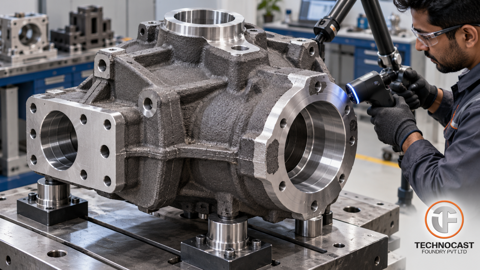
When engineers discuss sand-casting tolerances, the conversation often starts with:
“What tolerance grade can your foundry hold?”
That is usually the wrong first question.
A casting can meet its overall length and width requirements and still create serious manufacturing problems if:
- A bore is displaced
- A machined boss has insufficient stock
- Two bearing locations lose alignment
- A sealing face does not clean up
- The chosen locating surface is unstable
- Core movement affects an internal feature
For OEM engineers and procurement teams, the more useful question is:
Which features can remain as-cast, which features require machining, and how will the supplier demonstrate that every critical feature remains manufacturable?
A practical casting specification should separate:
As-cast dimensional requirements → Geometrical requirements → Machining allowance → Finished-component requirements
before tooling is approved.
Start With Function, Not the Tightest Tolerance Available
The objective of a casting drawing is not to make every dimension as precise as possible.
The objective is to control the dimensions that affect:
- Assembly
- Performance
- Machining
- Sealing
- Load transfer
while allowing economical casting tolerances elsewhere.
A good drawing review therefore begins by dividing the component into three groups.
1. Functional Interfaces
These may include:
- Bearing locations
- Mounting interfaces
- Locating diameters
- Sealing surfaces
- Mating faces
- Critical bore relationships
These features often become final machined characteristics.
2. Machining-Dependent Features
These are features that need sufficient casting stock and reliable tool access.
Examples include:
- Machined bosses
- Flanges
- Bore locations
- Bearing pads
- Datum faces
The critical question is not whether the raw surface is precise.
It is whether enough material exists to create the finished feature.
3. Noncritical As-Cast Geometry
External contours, ribs and clearance surfaces may not require precision machining.
Applying unnecessarily tight tolerances to these features can increase:
- Tooling cost
- Foundry rejection
- Inspection effort
- Part cost
without improving component function.
Dimensional Accuracy and Geometrical Accuracy Are Different
A common drawing mistake is focusing only on plus/minus dimensions.
Consider a bearing bore.
Its diameter could be correct, but its axis may still be incorrectly positioned.
Similarly:
A flange can have the correct thickness but insufficient flatness.
Two bosses can each have the correct individual diameter but the wrong relationship to each other.
This is why engineers should distinguish:
Size
from:
Position, orientation and form.
For a finished component, that may require GD&T controls such as:
- Position
- Flatness
- Perpendicularity
- Profile
- Runout
- Coaxial relationship
depending on the function.
Treat the Raw Casting and Finished Component Separately
A raw sand casting and a finished machined component should not be inspected as though they are the same manufacturing condition.
Consider a transmission housing.
The raw casting may require adequate control of:
- Overall geometry
- Boss location
- Wall thickness
- Core position
- Machining stock
After machining, the component may then require much tighter control of:
- Bearing bores
- Datum faces
- Bore relationships
- Mounting interfaces
The finished requirement should not automatically be imposed on the raw casting.
The manufacturing route should instead be:
Cast geometry accurately enough → Preserve machining stock → Locate correctly → Machine functional precision
This is one of the central principles of economical casting design.
ISO 8062-3 and Sand Casting Tolerances
ISO 8062-3 provides a structured framework for dimensional and geometrical tolerances and machining allowances for castings.
The source material correctly notes that the 2023 edition replaced the 2007 edition.
For an OEM drawing, do not simply write:
“ISO 8062-3”
without identifying the agreed edition where contractual clarity matters.
The engineering team and foundry should also agree exactly which parts of the standard apply.
Important Terms to Separate
Several different concepts are often incorrectly treated as the same thing.
DCTG — Dimensional Casting Tolerance Grade
This defines allowable dimensional variation for relevant as-cast dimensions.
It answers:
How much dimensional variation can this casting feature have?
GCTG — Geometrical Casting Tolerance Grade
This addresses general geometrical variation where applicable.
It relates to characteristics such as casting geometry rather than only nominal size.
RMAG — Required Machining Allowance Grade
This is part of the system used to establish machining allowance.
RMA — Required Machining Allowance
This is the actual stock required on a surface that will later be machined.
These values should not be confused.
A casting tolerance tells you how far a feature may vary.
Machining allowance tells you whether sufficient material remains to create the finished surface after that variation occurs.
Total Tolerance Band vs ± Tolerance
Another common source of misunderstanding is tolerance-table interpretation.
A table may list a total tolerance band.
That does not automatically mean the stated number applies:
+ value / – value
on each side.
For example, a total tolerance band of 4 mm is not necessarily:
+4 / –4 mm.
Before approving any supplier capability chart, establish whether the values represent:
- Total permissible variation
- Equal bilateral variation
- Unequal deviation
- Another drawing-specific convention
This avoids quoting and tooling decisions being made from different interpretations of the same number.
Sand Casting Process Influences Dimensional Capability
Not all sand-casting processes have identical dimensional behaviour.
Capability depends on:
- Moulding process
- Tooling
- Material
- Component size
- Geometry
- Core complexity
- Production volume
- Process control
The supplied SFSA guidance for comparable steel castings describes shell moulding as generally more dimensionally capable than no-bake and conventional green-sand routes.
However, this should not be converted into a universal statement such as:
“Shell moulding always achieves tolerance grade X.”
Production evidence matters more than the process name.
Shell Moulding
Shell moulding can provide advantages such as:
- Better mould rigidity
- Good surface quality
- Repeatable tooling
- Improved dimensional consistency
for suitable components.
But actual capability still depends on:
- Casting size
- Material
- Core arrangement
- Feature position
- Tool condition
No-Bake Moulding
No-bake processes are highly useful for:
- Larger components
- Heavy sections
- Complex core packages
- Lower-to-medium volume programs
Large dimensions and long spans may need particular attention.
For these castings, review:
- Distortion
- Core movement
- Long feature relationships
- Machining stock
rather than relying on a generic tolerance grade.
DISA High-Pressure Moulding
Automated high-pressure moulding can provide excellent production repeatability for suitable high-volume component families.
But a statement such as:
“DISA casting = this tolerance”
is still incomplete.
Request capability evidence from the actual:
- Line
- Tooling
- Material
- Component geometry
- Feature location
proposed for your program.
Process Name Is Not Process Capability
This principle is important enough to repeat:
Do not purchase a tolerance based only on the name of the moulding process.
A supplier should demonstrate capability using comparable components or production data.
For critical features, request evidence showing:
- Nominal requirement
- Actual measured distribution
- Sampling quantity
- Measurement method
- Production condition
where appropriate.
Material Changes Can Change Dimensional Behaviour
Do not automatically transfer an accepted tolerance strategy between materials.
For example:
Grey iron → Ductile iron
or:
Ductile iron → Carbon steel
may require another feasibility review.
Different materials can behave differently during:
- Solidification
- Cooling
- Heat treatment
- Stress relief
- Machining
The correct question is not:
“Which material is generally more accurate?”
It is:
“What capability has the supplier demonstrated for this material, geometry and process?”
Casting Size Also Matters
Large castings naturally create additional dimensional challenges.
Long spans may be influenced by:
- Mould movement
- Thermal contraction
- Pattern effects
- Distortion
- Heat treatment
This becomes particularly important when two functional features are located far apart.
Instead of controlling only each individual feature, engineers should identify the relationship between them.
Core-Controlled Dimensions Need Separate Attention
Internal casting geometry often depends on cores.
These may create:
- Internal passages
- Cavities
- Hollow sections
- Internal bores
Core position is affected by the design of:
- Core prints
- Supports
- Assembly
- Mould closure
A dimension controlled by a core may therefore behave differently from a dimension created entirely within one mould half.
Critical core-controlled features should be reviewed separately during DFM.
Do Not Ignore Core Shift
Suppose a casting contains a central passage.
The external casting dimension may be correct.
But if the core shifts, one wall can become thinner while the opposite wall becomes thicker.
This can affect:
- Structural performance
- Machining stock
- Pressure integrity
- Weight
Wall-thickness control can therefore be more important than the external envelope for some components.
Surface Finish Is Not Dimensional Tolerance
Another frequent specification problem is mixing dimensional accuracy and surface roughness.
They are different characteristics.
A component may have excellent dimensional accuracy but a relatively rough as-cast surface.
Similarly, a visually smooth surface may still be dimensionally incorrect.
Surface-finish requirements should therefore be defined separately.
Specify Ra Correctly
Where arithmetic average roughness is required, specify:
Ra
and define:
- Measurement location
- Measurement condition
- Whether the surface is as-cast, blasted or machined
Do not assume that:
RMS = Ra.
They are different parameters.
Blasting Can Change the Inspection Condition
If surface roughness matters, clarify whether it is measured:
- Before blasting
- After blasting
- After coating
- After machining
A casting inspected in two different surface conditions can produce different results.
The inspection condition should therefore be part of the specification.
Machining Allowance Is Not Just “Add 3 mm”
One of the biggest risks in casting-to-machining programs is poorly planned machining allowance.
Simply adding the same stock everywhere is not an engineering strategy.
Machining allowance needs to consider:
- Casting variation
- Core movement
- Distortion
- Fixture location
- Tool access
- Final tolerance
Use a Machining Stock Map
During DFM, mark every surface that will be machined.
For each one, review:
What is the nominal stock?
What is the minimum possible stock after casting variation?
What happens if the core moves?
What happens if the casting distorts?
The correct question is:
Will the surface completely clean up in the worst acceptable casting condition?
Datum Selection Can Determine Whether the Part Cleans Up
A casting may contain enough overall machining stock and still fail because it is located incorrectly in the fixture.
Suppose a gearbox housing has two critical bearing bores.
If machining is centred from an unstable external casting surface, one bore may receive too much cleanup while the other runs out of stock.
The datum strategy should therefore be considered during casting development.
This is one of the major benefits of connecting casting engineering with CNC machining.
Cast the Geometry. Machine the Precision.
This is a useful design principle for many industrial components.
Use the casting process to create:
- Complex shape
- Internal geometry
- Ribs
- Bosses
- Near-net structure
Use machining where functional precision is required.
Typical machined features include:
- Bearing seats
- Seal faces
- Precision bores
- Locating diameters
- Mounting faces
Trying to achieve every final fit directly from sand casting usually increases cost without creating a robust production strategy.
When Should You Add Finish Machining?
Machining should be considered when the required feature cannot be supported reliably in the as-cast condition.
Examples include:
- Precision bearing fits
- Sealing faces
- Shaft alignment features
- Tight positional relationships
- Fine surface finish
- Threaded interfaces
The engineering decision should consider both:
Technical requirement
and:
Supplier process capability.
How Should the Supplier Demonstrate Dimensional Conformity?
A tolerance commitment should be supported by an inspection plan.
Depending on the component, this may include:
- CMM
- Dedicated gauges
- Height measurement
- Bore gauges
- Fixtures
- Templates
- 3D scanning where applicable
The measurement method should match the characteristic being controlled.
What Should a Dimensional Report Contain?
A useful dimensional inspection report should include:
- Part number
- Drawing revision
- Characteristic identifier
- Nominal dimension
- Acceptance limit
- Actual measurement
- Inspection condition
Most importantly, distinguish:
Raw casting measurement
from:
Finished machined component measurement.
Without that distinction, a dimensional report can create more confusion than confidence.
Prototype Approval Is Not Production Capability
One successful prototype proves that the geometry is possible.
It does not necessarily prove that the manufacturing process is stable.
Production approval should consider:
- Repeated measurements
- Tooling condition
- Sampling plan
- Inspection frequency
- Reaction plan
- Tool maintenance
For critical characteristics, process capability evidence may be required after stable production begins.
Tooling Wear Changes Casting Dimensions
Pattern and core tooling do not remain dimensionally perfect forever.
Over time, tooling can experience:
- Wear
- Damage
- Repair
- Modification
These changes can influence casting geometry.
The supplier should therefore maintain:
- Tool identification
- Maintenance records
- Revision control
- Inspection after significant repair
What Happens After Tooling Repair?
The purchase specification should define change-notification requirements.
Depending on component risk, certain changes may require:
- Dimensional requalification
- Machining trial
- First-article inspection
- Customer approval
Relevant changes may include:
- Pattern repair
- Core-box repair
- Material change
- Heat-treatment change
- Moulding-line change
- Manufacturing-location change
Do not allow these decisions to depend entirely on informal supplier judgement.
Connecting Sand Casting and CNC Machining
For OEM programs requiring machined components, casting tolerance and machining tolerance should be reviewed together.
Technocast’s established manufacturing capability includes ferrous casting processes along with CNC machining and dimensional inspection.
For suitable programs, this allows the engineering discussion to connect:
Casting tolerance → Machining allowance → Datum strategy → CNC machining → Final dimensional verification
rather than treating the raw casting and machined component as independent purchases.
How to Discuss Tolerances With Technocast
For a new casting, provide:
- Casting drawing
- Finished-component drawing
- 3D model where available
- Material grade
- Single-piece weight
- Annual volume
- Critical characteristics
- Machined surfaces
- Applicable ISO 8062-3 requirements
The feasibility review can then identify:
- Appropriate moulding route
- As-cast requirements
- Machining stock
- Datums
- Final inspection strategy
before tooling commitment.
Sand Casting Tolerance RFQ Checklist
Before releasing your RFQ, define:
Material
Specify the exact grade.
Drawing Condition
Clearly identify:
- Casting drawing
- Finished-component drawing
Standard
State the applicable ISO 8062-3 edition where used.
DCTG / GCTG
Define only where appropriate and agreed.
Machined Surfaces
Mark them clearly.
Machining Allowance
Agree stock based on process and geometry.
Critical Characteristics
Identify:
- Bearing features
- Sealing surfaces
- Datum relationships
- Positional requirements
Core-Controlled Features
Identify separately where required.
Surface Finish
Specify Ra and measurement condition where functionally necessary.
Inspection
Define how relevant characteristics will be measured.
Production Approval
Specify any required:
- First article
- Dimensional layout
- Capability evidence
Change Control
Define notification requirements for:
- Tooling changes
- Material changes
- Process changes
Conclusion
Sand-casting tolerance should not be treated as one number applied to an entire component.
A good tolerance strategy answers four separate questions:
What can remain as-cast?
What must be machined?
How much machining stock is required?
How will the final functional relationship be verified?
The best casting specification therefore connects:
Process capability + Geometry + Material + Machining allowance + Datum strategy + Inspection
before tooling is released.
For engineers, this avoids over-tolerancing noncritical surfaces.
For procurement, it creates comparable supplier quotations.
For the foundry, it creates a manufacturable definition of acceptance.
And for the OEM, it reduces the risk of discovering after machining that a dimensionally acceptable raw casting cannot become an acceptable finished component.
Request a Sand-Casting Feasibility Review
For a new or re-sourced casting, send Technocast:
- Casting drawing
- Finished-component drawing
- 3D model
- Material grade
- Single-piece weight
- Annual volume
- Critical characteristics
- Machining requirements
- Applicable tolerance standard
The component can then be reviewed for moulding route, dimensional feasibility, machining-stock strategy and final inspection requirements before tooling is approved.
Frequently Asked Questions
What tolerance can sand casting achieve?
There is no single tolerance for every sand casting. Capability depends on moulding process, material, component size, geometry, core design, tooling and production conditions.
Is shell moulding more accurate than conventional sand casting?
For comparable suitable components, shell moulding can offer improved dimensional repeatability and surface finish. Actual capability should still be proven using supplier data.
What is ISO 8062-3?
ISO 8062-3 provides a framework for dimensional and geometrical casting tolerances and machining allowances. The drawing should identify the agreed edition where needed.
What is the difference between casting tolerance and machining allowance?
Casting tolerance describes permitted dimensional variation. Machining allowance is the material stock provided so the final machined feature can be produced despite that variation.
Should every casting dimension have a tight tolerance?
No. Tight tolerances should be concentrated on functional and manufacturing-critical requirements. Unnecessarily tight control of noncritical geometry increases cost and rejection risk.
Why does core shift matter?
Core movement can alter internal geometry and wall thickness even when external casting dimensions remain acceptable.
Can bearing seats remain as-cast?
Precision bearing seats normally require machining because they often need controlled fits, surface finish and positional relationships beyond typical as-cast capability.
What should I provide for a tolerance feasibility review?
Provide the casting and finished drawings, material, production volume, critical features, machining surfaces and applicable tolerance requirements.
Related at Technocast: CNC machine shop · Quality and certifications
Read next: Casting wall thickness design rules · Casting and machining from one supplier