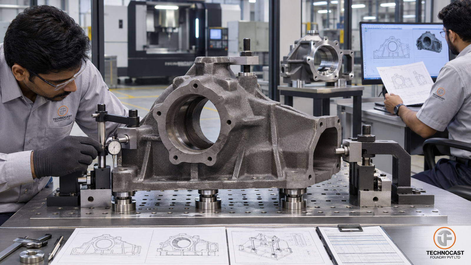
A casting drawing for machining should answer one practical manufacturing question:
How will the supplier convert a variable rough casting into an accurately located, machined and inspected finished component?
That requires more than adding machining symbols to a casting drawing.
The drawing package needs to connect:
Raw casting → Rough locating strategy → Machining allowance → First CNC setup → Finished datums → Critical features → Final inspection
For OEM engineers, this interface is important because many apparent “machining problems” actually begin earlier—with casting variation, core position, insufficient stock or an unsuitable locating strategy.
At Technocast Foundry Pvt. Ltd., this connection is central to our approach:
One stop solution, from casting to ready-to-fit parts.
When casting, heat treatment, CNC machining and dimensional inspection are considered as one manufacturing route, decisions made at the casting stage can be reviewed against the requirements of the finished component.
Why Use Separate Casting and Finished-Part Drawings?
The raw casting and finished component represent two different manufacturing conditions.
They should be defined accordingly.
The Casting Drawing
The casting drawing should establish the geometry required before machining.
Depending on the component, it may identify:
- Raw casting geometry
- Machining stock
- As-cast surfaces
- Rough locating pads or datum-target areas
- Material
- Relevant casting tolerances
- Core-related features
- Parting considerations
- Heat-treatment condition where applicable
The Finished Machined Drawing
The finished drawing should define the component in its functional condition.
Typical requirements include:
- Finished datums
- Bearing fits
- Bore sizes
- Hole locations
- Threads
- Sealing interfaces
- GD&T
- Surface texture
- Critical characteristics
The two drawings should be linked by controlled part numbers and compatible revisions.
The manufacturing team should understand exactly which document controls:
as-cast condition
and which controls:
finished condition.
Do Not Leave the Blank-to-Finished Relationship Undocumented
An integrated supplier may develop the casting drawing from the customer’s finished-component model.
That does not remove the need to agree on the relationship between the two manufacturing states.
Before tooling is released, review:
- Which surfaces will be machined
- How much stock will remain
- How the raw casting will be located
- Where final datums will be created
- Which features remain as-cast
- How critical geometry will be inspected
These assumptions become increasingly important on components such as:
- Gearbox housings
- Differential housings
- Pump bodies
- Valve bodies
- Bearing housings
- Axle components
where several machined features must maintain a relationship to one another.
Start With Functional Datums—Then Work Backwards
Datum strategy should begin with how the finished component functions in assembly.
Suppose a gearbox housing is assembled using:
- One mounting face
- One locating side face
- One end reference
Those finished features may eventually become Datums A, B and C.
But those finished surfaces do not exist when the raw casting enters the first machining setup.
The manufacturing engineer therefore needs another question answered:
How will the rough casting be located accurately enough to create those finished datums?
That is the casting-to-machining datum problem.
Rough Casting Surfaces Are Not Precision Surfaces
Sand-cast geometry naturally contains manufacturing variation.
Depending on the process and component, this can include variation associated with:
- Tooling
- Moulding
- Parting
- Core location
- Cooling
- Distortion
A rough irregular casting surface may therefore be a poor choice for unrestricted planar contact.
For difficult components, controlled locating pads or datum targets can create a more repeatable initial setup.
Use Datum Targets Where Appropriate
Instead of asking a fixture to contact a large irregular cast surface, the drawing or manufacturing plan can identify smaller controlled contact locations.
These may be:
- Cast-in pads
- Defined target areas
- Local locating bosses
The exact strategy depends on the component.
Good target locations should avoid unstable areas such as:
- Flash
- Parting-line mismatch
- Irregular edges
- Highly variable surfaces
The objective is repeatability—not simply finding three places where a fixture can touch the casting.
Understand the 3-2-1 Locating Principle
Where suitable, a 3-2-1 locating strategy can be used to constrain the six degrees of freedom of a rigid workpiece.
Conceptually:
Primary location
Three contacts establish the primary reference.
Secondary location
Two contacts establish the secondary orientation.
Tertiary location
One contact completes the location.
But this principle should not be applied mechanically.
The actual fixture must also consider:
- Component rigidity
- Cutting forces
- Accessibility
- Clamping
- Casting variation
Do Not Clamp a Distorted Casting Flat
A common fixture mistake is supporting a thin or distorted casting in a way that forces it into an artificial position during machining.
Imagine a housing with a slightly distorted wall.
If the fixture clamps that wall completely flat:
- The component is machined while elastically distorted.
- The clamps are released.
- The casting springs back.
- Machined features may move relative to each other.
Fixture supports should therefore stabilise the casting without unnecessarily deforming it.
Locate Near Machining Loads
Fixture support must also consider cutting forces.
If a large machining load is applied far from a supporting point, the casting can:
- Deflect
- Vibrate
- Move
during machining.
The fixture strategy should therefore consider the complete relationship between:
Locator → Clamp → Cutting load → Component stiffness
rather than treating datums as a drawing-only decision.
Separate Rough Locators From Finished Datums
This is one of the most important concepts in casting machining.
The features used to hold the raw casting are not necessarily the same features used to define the finished part.
A typical sequence may be:
Rough casting locators → First machining setup → Establish finished Datum A → Establish B/C → Subsequent machining → Final inspection
That datum transfer should be intentional.
Do not allow the manufacturing process to silently change its reference system halfway through production.
Document the Datum Transfer
The drawing and process review should establish:
- What locates the raw casting
- Which operation creates the first finished datum
- Which features establish the remaining datum reference frame
- Which later operations use those finished references
- Which datum system final inspection uses
This provides a common reference between:
Foundry → CNC machining → CMM inspection
and reduces disagreement when a feature is found outside tolerance.
Plan Machining Allowance Surface by Surface
Machining allowance should not automatically be applied as one universal number to every surface.
The actual stock needed can vary according to:
- Material
- Casting process
- Component size
- Casting orientation
- Surface position
- Core location
- Distortion tendency
- Required cleanup
- Machining method
ISO 8062-3:2023 provides a framework covering general casting tolerances and machining allowance grades, but actual manufacturing capability still needs to be agreed for the component.
Agree the Moulding Route Before Freezing Stock
Different manufacturing routes can produce different dimensional behaviour.
For Technocast programs, potential moulding routes may include:
- DISA high-pressure green-sand moulding
- Shell moulding
- No-bake moulding
The machining-stock discussion should therefore follow the proposed manufacturing route.
For example:
| Moulding Route | Machining Review Focus |
|---|---|
| DISA high-pressure moulding | Tooling repeatability, locating consistency and cleanup across machined features |
| Shell moulding | Local stock, core relationship and controlled functional surfaces |
| No-bake moulding | Support, large-span variation, distortion and machining sequence |
This table is qualitative.
It should not be converted into universal millimetre allowances.
Do Not Copy Machining Allowance From Another Casting
Two apparently similar components can require different machining stock.
Differences may include:
- Material
- Weight
- Orientation
- Geometry
- Moulding process
- Core arrangement
A stock value used successfully on one housing should not automatically be copied to another.
Ask for component-specific feasibility.
Specify Stock Clearly
Where machining allowance is critical, the drawing should remove ambiguity.
For example, identify whether an allowance on a diameter is:
radial
or:
diametral.
Also distinguish between different casting faces where relevant.
A cope-facing surface may not behave identically to a drag-facing or vertical surface.
The machining review should identify where local exceptions are necessary.
Machining Allowance Is Not Pattern Shrinkage Allowance
These are different manufacturing concepts.
Pattern shrinkage compensation
Accounts for dimensional change as the metal solidifies and cools.
Machining allowance
Provides material that will intentionally be removed during machining.
Do not combine them into one unspecified dimensional addition.
Review Core Shift With Machining Stock
For a cored housing, enough stock on the external surface does not guarantee that the finished wall will be acceptable.
Consider the combined variation:
Core location + Casting variation + Machining location + Material removal
A bore may completely clean up while leaving insufficient wall to an internal passage.
The drawing review should therefore consider both:
external machining stock
and:
internal remaining wall.
Heat Treatment Must Be Included in the Datum Strategy
If heat treatment occurs between casting and final machining, it may influence dimensional stability.
The manufacturing route should define whether the component will be:
- Heat treated before machining
- Rough machined before treatment
- Finish machined after treatment
depending on the approved material/process route.
If dimensional stabilisation is required, establish its position before final precision datums are created.
Otherwise, a feature machined accurately before treatment may move afterwards.
Critical Features Belong on the Finished Drawing
Not every surface needs the tightest tolerance.
Focus precision where component function requires it.
Bearing Bores
Define requirements such as:
- Diameter/fit
- Form
- Axis location
- Relationship to adjacent bearing seats
For gearbox or differential housings, bore-to-bore relationships may be more important than either bore considered independently.
Sealing Faces
Define:
- Flatness
- Surface texture
- Relevant edge condition
- Relationship to the datum system
where function requires them.
Mounting Interfaces
Depending on function, these may require control of:
- Flatness
- Parallelism
- Perpendicularity
relative to the appropriate references.
Hole Patterns
Use clearly defined basic locations and appropriate position controls where required.
Avoid tolerancing every X and Y coordinate independently when the real design intent concerns the hole pattern relative to the assembly datum system.
Threads
Define:
- Thread standard
- Size
- Class
- Usable depth
- Gauging requirement
where applicable.
“Tapped hole” alone is not a complete production requirement.
Use GD&T to Communicate Function
ASME Y14.5 provides the established language for communicating GD&T requirements in engineering product definition. The currently effective edition is Y14.5-2018, reaffirmed in 2024.
The objective is not to add more feature-control frames.
It is to communicate design intent clearly.
A well-prepared drawing should tell manufacturing and inspection:
- Which feature controls orientation
- Which controls location
- Which surfaces are functionally related
Do Not Confuse Flatness With Orientation
Flatness controls the form of a surface.
It does not require a datum reference.
Perpendicularity, parallelism and position are different controls and may require appropriate datum references.
This distinction matters when the CMM inspection strategy is created.
CMM Inspection Should Use the Drawing Datum Frame
A component can produce very different measurement results depending on how the inspection software aligns it.
For acceptance inspection, avoid replacing the drawing’s datum system with an unrestricted mathematical best-fit unless that method has been explicitly agreed.
The CMM strategy should reproduce the intended datum reference frame where technically applicable.
At Technocast, connecting CNC machining and CMM dimensional inspection allows datum strategy to be considered as part of the manufacturing route rather than only after the component is machined.
Design for Inspection Access
A tolerance has limited value if it cannot be reliably measured.
During drawing review, consider whether:
- Datum surfaces are accessible
- CMM probes can reach the required feature
- Bore gauges can enter correctly
- Thread gauges have adequate access
- Fixture hardware blocks inspection
Manufacturing and inspection accessibility should be reviewed together.
Surface Texture Should Be Local, Not Universal
Do not apply a tight Ra requirement to an entire casting when only a few surfaces require it.
Specify surface texture where function demands it, such as:
- Sealing surfaces
- Bearing locations
- Precision mounting interfaces
Leave suitable nonfunctional surfaces explicitly as-cast where possible.
This reduces unnecessary machining and cost.
Example: Ductile-Iron Gearbox Housing
Consider a ductile-iron housing containing:
- Two bearing seats
- Main mounting flange
- Gasket face
- External ribs
- Threaded mounting holes
The finished drawing defines:
Datum A: machined main mounting face
Datum B: machined side locating face
Datum C: machined end reference
But none of these finished surfaces exists on the raw casting.
The casting design therefore includes controlled rough locating pads for the first machining setup.
Setup 1 — Locate the Raw Casting
Place the rough housing on agreed locating targets.
The objective is to establish adequate stock distribution across the future machined features.
The first operation can create:
- Datum A
- Initial reference features
Setup 2 — Transfer to Finished Datums
Once Datum A and associated reference features exist, subsequent machining can use them rather than the original irregular casting surfaces.
Additional operations create:
- Datums B and C
- Bearing bores
- Mounting features
Final Operations
Finish:
- Bearing seats
- Gasket surface
- Hole patterns
- Threads
according to the finished drawing.
Final Inspection
CMM inspection uses the finished datum reference frame.
The inspection confirms:
- Bearing-axis relationship
- Hole position
- Mounting-face relationships
- Applicable GD&T
while other suitable measurement methods verify:
- Bore size
- Threads
- Surface texture
as required.
This creates a documented transition from:
Raw casting location → Manufacturing datums → Functional datums → Inspection datums
First-Off Components Should Confirm the Machining Strategy
Do not wait for serial production to discover that machining stock is marginal.
Early castings should verify:
- Stock distribution
- Fixture stability
- Datum repeatability
- Complete surface cleanup
- Core relationship
- Machining accessibility
The first-off results can then confirm whether the drawing and process assumptions are realistic.
What Should Be Included in an RFQ-Ready Drawing Package?
Before sending the RFQ, provide:
Drawing Control
- Casting drawing
- Finished drawing
- Compatible revision status
- 3D model where applicable
Material
- Material grade
- Delivery condition
- Required heat treatment
- Relevant hardness/property requirements
Raw Casting Location
- Rough locating pads
- Datum targets where used
- Initial fixture assumptions
Machining
- Machined surfaces
- Feature-specific stock
- As-cast surfaces
- Finished datums
- Critical dimensions
- GD&T
- Threads
- Local surface-texture requirements
Inspection
- Critical characteristics
- CMM reporting expectations
- Sampling
- Applicable functional testing
- Required records
Finishing
Where applicable:
- Coating specification
- Masking boundaries
- Condition in which dimensions apply
Nonconformance
Define:
- Notification
- Containment
- Repair approval
- Concession authority
What If Machining Exposes a Casting Defect?
The decision process should be agreed before production.
If machining exposes:
- Cavity
- Porosity
- Inclusion
- Unexpected internal passage
do not make an uncontrolled machining adjustment.
Preserve the part and evaluate:
- Defect location
- Core position
- Casting geometry
- Machining datum
- Fixture
- Tool path
- Remaining wall
Then obtain the required engineering disposition.
The issue may not be machining alone.
Who Approves a Datum Change?
Datum changes should not be treated as ordinary shop-floor optimisations when they can affect functional relationships.
If a supplier proposes a different locating or datum strategy, request:
- Marked-up drawing
- Manufacturing rationale
- Dimensional impact
- Inspection impact
and obtain approval from the responsible design authority.
Should Coating Be Included in Dimensional Acceptance?
That depends on the component specification.
The drawing should establish whether a dimension or fit applies:
- Before coating
- After coating
and which areas must be masked.
Bearing seats, sealing surfaces, threads and precision datum contacts may require specific protection.
Technocast: Connecting Casting and Machining
At Technocast Foundry Pvt. Ltd., our broader manufacturing approach is:
One stop solution, from casting to ready-to-fit parts.
The advantage of connecting casting and CNC machining is not simply reducing the number of suppliers.
The engineering value comes from connecting:
Casting process → Machining stock → Rough locators → CNC datum strategy → Finished geometry → CMM verification
within one coordinated manufacturing route.
That feedback is particularly useful when:
- Stock does not clean up
- A bore approaches a core passage
- Heat treatment affects geometry
- A fixture exposes casting variation
- CMM results identify a recurring dimensional trend
Rather than treating each issue as belonging to a separate supplier, the manufacturing route can be reviewed as one system.
Send Us Your Drawing for a Machinability Review
For a new or re-sourced machined casting, send:
- Casting or finished drawing
- 3D model
- Material grade
- Single-piece weight
- Annual volume
- Finished datums
- Critical tolerances
- Machined surfaces
- Heat-treatment requirements
- Inspection requirements
- Required final delivery condition
The objective is to resolve the blank-to-finished relationship before tooling and machining assumptions become expensive to change.
Conclusion
A good machining drawing does more than specify final dimensions.
For a cast component, it needs to work with a manufacturing plan that explains:
Where does the rough part locate?
How much material needs to remain for machining?
Which operation establishes the finished datum system?
Which features actually require precision?
How will those requirements be verified?
When these decisions are made early, the drawing becomes more than documentation.
It becomes a manufacturing handover from:
Casting to ready-to-fit part.
Frequently Asked Questions
Should casting and machined dimensions be on the same drawing?
They can be managed in different ways, but for complex machined castings, clearly linked casting and finished-component definitions often make the different manufacturing states easier to control.
What is a casting datum target?
It is a defined contact or target location used to establish a repeatable reference on a rough casting where a large irregular as-cast surface may not provide stable location.
How much machining allowance should be added to a casting?
There is no universal value. It depends on material, casting process, geometry, size, orientation, distortion and the surface being machined. Agree it with the foundry for the actual part.
Should machining allowance be the same on every surface?
Not necessarily. Different surfaces may require different stock because of orientation, process variation, core location and cleanup requirements.
What is datum transfer in casting machining?
Datum transfer is the planned change from the temporary references used to locate the rough casting to the finished functional datums created during machining.
Can CMM inspection use best-fit alignment instead of drawing datums?
Not automatically for acceptance inspection. The inspection alignment should follow the drawing’s intended datum reference system unless another method is specifically agreed.
Should heat treatment happen before or after machining?
The sequence depends on the material and approved manufacturing route. It should be agreed before final machining and datum strategy are established.
Why should the foundry review the machining drawing?
Casting geometry, core position, machining allowance, heat-treatment movement and fixture strategy all influence whether the finished component can actually meet the drawing.