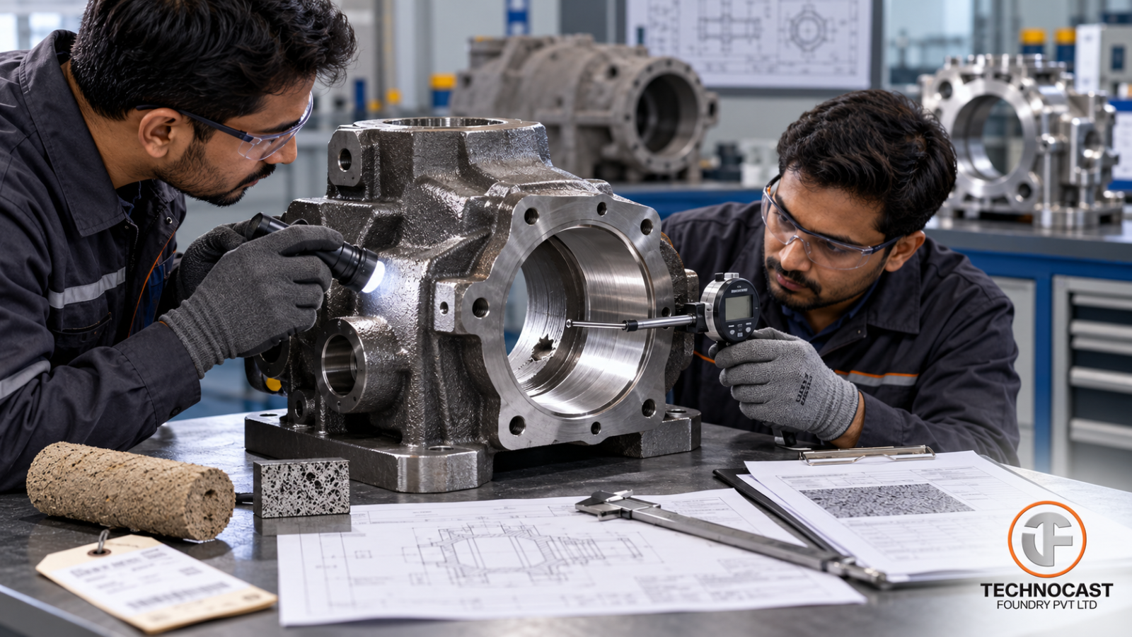
A critical casting can look acceptable after pouring and still fail later during machining.
A drilled hole may open into an internal passage.
A bearing bore may expose a hidden cavity.
A pressure wall may become thinner than intended.
When that happens, the problem cannot be treated simply as:
“Porosity found after machining.”
The real question is:
What caused the condition — core movement, casting variation, machining datum, insufficient wall allowance, shrinkage or another internal defect?
For safety- and quality-critical components, that question needs a documented engineering answer, not an improvised repair.
At Technocast Foundry Pvt. Ltd., our approach is built around:
One stop solution, from casting to ready-to-fit parts.
That means looking at quality across the complete manufacturing route:
Material → Casting → Heat Treatment → Machining → Inspection → Final Component
rather than treating defects only as a foundry-floor problem.
Why Critical Iron Castings Need More Than Final Inspection
Critical components may include:
- Pressure boundaries
- Load-bearing sections
- Bearing locations
- Sealing surfaces
- Minimum wall requirements
- Precision-machined features
A component can pass visual inspection and still reveal a defect after machining.
For this reason, a good quality plan should start from:
Service requirement → Critical feature → Possible failure → Preventive control → Verification → Acceptance decision
This is the planning sequence identified in the supplied research.
The objective is not simply to find defective parts.
It is to understand what must be controlled before production begins.
First Define What the Defect Actually Is
One of the biggest mistakes during casting investigation is calling every internal cavity:
“Porosity.”
Different conditions have different mechanisms.
The source separates them into practical categories.
Gas Porosity
Gas-related voids may be associated with:
- Melt condition
- Mould moisture
- Core binder
- Venting
- Metal handling
- Pouring conditions
The investigation should determine:
- Where the voids occur
- Whether they are isolated or repeated
- Whether they intersect machined or functional surfaces
Shrinkage
Shrinkage is connected to solidification and feeding.
Higher-risk areas may include:
- Heavy bosses
- Thick junctions
- Rib intersections
- Isolated heavy sections
- Abrupt wall transitions
Corrective action should therefore examine feeding and solidification behaviour.
Inclusions
Inclusions involve unwanted material within the casting.
The investigation should identify:
- Type
- Extent
- Location
- Relationship to critical features
before deciding corrective action.
Unintended Hole Breakthrough
This is especially important for machined housings.
A machined or drilled feature may unexpectedly intersect:
- Internal passage
- Casting cavity
- Exterior wall
Possible causes include:
- Core shift
- Casting variation
- Wrong machining location
- Insufficient remaining wall
- Internal unsoundness
The source specifically recommends not assuming every exposed hole is porosity.
Record the Evidence Before Changing the Process
Before deciding on corrective action, record:
- Exact defect location
- Appearance
- Casting orientation
- Machining operation
- Heat or batch
- Number of affected parts
Where possible, preserve both:
- Failed components
- Acceptable components
This allows the engineering team to compare production conditions instead of making changes based on one isolated part.
Control Gas Sources Before Pouring
The supplied research identifies excessive gas, solidification shrinkage or a combination of both as general causes of casting porosity.
For gas-related risk, process control should include appropriate monitoring of:
- Charge material
- Melt preparation
- Mould condition
- Core condition
- Binder/storage conditions
- Ladle preparation
- Metal handling
- Pouring temperature
- Pouring continuity
Each important parameter should have:
Operating range + Responsible owner + Reaction plan
The objective is to prevent uncontrolled process variation before the defect occurs.
Do Not Adjust Pouring Temperature From a Photograph Alone
When a defect appears, simply changing pouring temperature may not address the true cause.
Compare:
Affected production
against:
Acceptable production
using actual records.
This may include:
- Heat chemistry
- Mould conditions
- Core batch
- Pouring parameters
- Time sequence
Corrective action should come from evidence.
Material Verification and Defect Detection Are Different
For critical castings, the quality plan may require:
- Chemistry
- Mechanical properties
- Hardness
- Microstructure
But these checks answer different questions from internal-defect inspection.
Spectrometry can confirm chemistry.
It does not prove that the casting has no shrinkage cavity.
Likewise, CMM can confirm geometry.
It does not prove internal soundness.
Each control method should have a clearly defined purpose.
Core Position Can Decide Whether the Finished Part Passes
For cored housings, external dimensions alone may not be enough.
The casting can meet its outside dimensions while the core is displaced internally.
The source gives a useful relationship:
Passage position + Casting variation + Machining location + Material removal → Remaining wall
This becomes important around:
- Drilled ports
- Bearing bores
- Hydraulic passages
- Thin structural sections
Review Core Control
For critical internal geometry, review:
- Core-box condition
- Core dimensions
- Core prints
- Core seating
- Core support
- Assembly verification
Ask one important question:
If the core moves to its permitted limit, which wall becomes the thinnest?
That location may be more important than the overall casting dimensions.
Define Minimum Remaining Wall Where Required
If a wall is functionally critical, specify the minimum requirement.
This may be particularly important around:
- Pressure sections
- Drilled passages
- Machined ports
- Bearing housings
The final acceptance condition should consider the geometry after machining — not only the raw casting.
Feeding and Solidification Must Be Designed Around Critical Sections
Shrinkage prevention starts with understanding where the casting will solidify last.
The foundry should be able to explain:
- Which areas are thermally heavy
- How they receive feed metal
- Where feeders are located
- Whether chills are required
- Whether geometry changes are recommended
The supplied source highlights a ductile-iron study where insufficient feeding was identified as the mechanism behind shrinkage.
The correct lesson is not:
“Add more feeders everywhere.”
It is:
Understand where and why feeding is insufficient.
Machining Allowance Must Be Part of the Soundness Review
A casting may contain a soundness-risk region that appears harmless in the raw component.
Machining may later move the finished surface closer to that region.
Therefore review:
Soundness risk + Machining stock + Final surface
together.
This is another reason casting and machining engineering should not operate independently.
Simulation Should Lead to Manufacturing Decisions
Simulation can be useful in identifying:
- Filling risk
- Hot spots
- Shrinkage risk
- Feeding behaviour
But the useful output is not:
“Simulation completed.”
Ask:
- What risk was identified?
- Where was it located?
- What design or process change was proposed?
- How will the prediction be verified?
For critical areas, the best result is a marked-up drawing connecting:
Risk zone → Process control → Inspection method
Validate the Manufacturing Method on Real Components
Simulation should be followed by physical validation.
A useful qualification sequence is:
Predict → Manufacture → Inspect → Compare
The source describes this approach through trial castings after modifying the feeding arrangement.
Depending on component criticality, first-article validation may include:
- Dimensional inspection
- Targeted NDT
- Metallography
- Sectioning
- Functional testing
Use the Correct Inspection Method for the Correct Risk
No inspection method can answer every quality question.
Visual Inspection
Useful for accessible surface conditions.
It cannot verify internal soundness.
Magnetic Particle Testing
For suitable ferromagnetic components, MT/MPI can detect specified:
- Surface
- Near-surface
discontinuities.
Ultrasonic Testing
UT can support internal examination where:
- Material
- Geometry
- Access
- Calibration
- Coverage
make the method suitable.
Acceptance criteria should be defined.
Radiography or CT
These methods may be relevant when specific internal discontinuities or geometry need volumetric evaluation.
They should be specified only where the component and acceptance plan require them.
CMM Inspection
CMM verifies dimensional and geometrical requirements.
It can check:
- Bore position
- Datum relationships
- Surface position
- GD&T
but it does not replace internal-defect inspection.
The source makes this distinction clear by assigning different questions to each inspection method.
Inspection Must Continue After Machining
Some defects remain hidden until machining removes the external material.
This makes post-machining inspection important for critical features.
Potential examples include:
- Bearing bores
- Pressure ports
- Sealing faces
- Machined bosses
The source specifically notes that subsurface pinholes may escape visual inspection before machining.
What Should Happen if a Hole Breaks Through?
If machining exposes an unexpected cavity:
- Stop the affected operation.
- Segregate affected components.
- Preserve traceability.
- Record defect location.
- Obtain authorised engineering disposition.
Then compare:
- Core position
- Raw casting geometry
- Fixture location
- Machining datum
- Program revision
- Tool path
- Exposed cavity location
Do not simply reduce drilling depth and continue.
That may hide the symptom without fixing the underlying requirement.
Write Acceptance Criteria by Critical Zone
Avoid vague statements such as:
“No casting defects allowed.”
Instead define requirements based on the component.
Where applicable, define:
- Discontinuity type
- Permitted size or extent
- Location
- Inspection coverage
- Acceptance criteria
- Repair restrictions
For a pressure-containing component, pressure/leak-test requirements should be defined separately where applicable.
Repairs Must Be Controlled
Methods such as:
- Welding
- Plugging
- Impregnation
- Other repairs
should not become informal production decisions.
The customer specification should define whether each method is:
- Permitted
- Restricted
- Subject to approval
- Prohibited
Critical-component disposition requires documented authority.
CMM Inspection Should Follow Functional Datums
CMM inspection should reflect how the component actually functions.
If a gearbox housing uses:
- Mounting face
- Bearing bore
- Locating hole
as functional datums, dimensional verification should follow the appropriate datum strategy.
This provides more useful evidence than measuring dimensions independently without their functional relationship.
From Casting to Ready-to-Fit Parts
This is where Technocast’s integrated manufacturing approach becomes important.
At Technocast Foundry Pvt. Ltd., our focus is:
One stop solution, from casting to ready-to-fit parts.
For suitable iron-casting programs, this allows manufacturing decisions to be connected across:
Casting → Heat Treatment → CNC Machining → CMM Inspection → Applicable NDT → Finished Component
instead of treating each stage as an unrelated supplier activity.
Our established relevant capabilities include:
- Grey iron casting
- Ductile iron casting
- Multiple moulding routes
- Spectrometry
- Heat treatment
- CNC machining
- CMM inspection
- Ultrasonic testing where applicable
The value is not simply that several manufacturing operations are available.
The value is that the casting and finished-part requirements can be reviewed together.
Casting Allowance and Machining Datum Should Be Connected
Imagine machining exposes a cavity around a critical bore.
An integrated investigation can compare:
- Casting geometry
- Machining allowance
- Core position
- Heat-treatment movement
- Fixture datum
- CNC program
- Inspection results
This helps identify whether the root cause belongs to:
- Casting design
- Foundry process
- Machining setup
- Tolerance stack
rather than automatically blaming the final operation.
Traceability Should Follow the Component
For critical components, traceability may need to connect:
Heat → Casting batch → Drawing revision → Heat treatment → Machining → Inspection → Dispatch
The exact requirement depends on the customer program.
But if an issue appears, the manufacturer should be able to determine which production population may be affected.
Quality Is Not Final Sorting
Inspection has two jobs:
Prevent unacceptable components from reaching the customer
and:
Generate evidence for eliminating the root cause.
If UT repeatedly finds indications in one area, the long-term solution should not be simply:
“Inspect more.”
The foundry should review:
- Feeding
- Geometry
- Moulding
- Process control
to understand why the condition occurs.
The goal is prevention.
Practical Critical Iron Casting Quality Checklist
Before production release, confirm:
Material
- Exact material grade
- Delivery condition
- Required chemistry
- Mechanical properties
- Hardness/microstructure where required
Critical Areas
Identify:
- Pressure boundaries
- Load paths
- Sealing surfaces
- Bearing locations
- Minimum walls
Drawings
Control both:
- Raw casting drawing
- Finished component drawing
Machining
Review:
- Stock
- Datums
- Fixtures
- Tool paths
- Critical clean-up conditions
Process Controls
Define controls for:
- Melt
- Mould
- Cores
- Pouring
Inspection
Define:
- Method
- Location
- Coverage
- Acceptance
CMM
Link characteristics to drawing datums.
Post-Machining Inspection
Identify which newly exposed surfaces require inspection.
Traceability
Define:
- Heat identification
- Batch identification
- Record linkage
Nonconformance
Define:
- Segregation
- Containment
- Repair approval
- Concession authority
What Should Trigger Requalification?
Relevant process changes should trigger review.
Examples may include:
- Pattern modification
- Core-box modification
- Gating changes
- Feeding changes
- Material changes
- Machining-datum changes
- Production transfer
The required requalification should match the risk created by the change.
Investigating Intermittent Defects
Intermittent defects need comparison.
Preserve:
- Affected parts
- Acceptable parts
Then compare:
- Heat
- Mould conditions
- Core batch
- Pouring records
- Machining setup
- Inspection findings
Look for a repeatable relationship before modifying the process.
One Stop Solution, From Casting to Ready-to-Fit Parts
For us, defect prevention is not limited to producing a visually acceptable raw casting.
The real measure is whether the component reaches its agreed final condition.
That means controlling the relationship between:
Metallurgy
Casting geometry
Core position
Machining allowance
Machining datums
Inspection
Traceability
and the finished component.
That is why Technocast’s manufacturing approach is built around:
One stop solution, from casting to ready-to-fit parts.
The customer needs more than a casting.
The customer needs confidence that the finished component meets its intended function.
Discuss Your Critical Casting Requirement With Technocast
For a new or re-sourced critical component, share:
- Casting drawing
- Finished-part drawing
- Material specification
- Single-piece weight
- Annual volume
- Service conditions
- Critical features
- Minimum wall requirements
- Machining scope
- Inspection requirements
- Required final delivery condition
Our objective is to review the complete route from raw casting through machining and inspection, so quality risks are addressed before they become finished-component failures.
Technocast Foundry Pvt. Ltd. — One stop solution, from casting to ready-to-fit parts.
Frequently Asked Questions
What are the most common defects in critical iron castings?
Common conditions include gas porosity, shrinkage, inclusions and unintended breakthrough into an internal passage or cavity.
Is every hole exposed after machining caused by porosity?
No. The cause may be core movement, machining position, insufficient remaining wall or another internal discontinuity.
Why can defects appear only after machining?
Machining removes surface material and can expose subsurface cavities or move a functional surface closer to an internal passage.
Can CMM detect porosity?
No. CMM verifies dimensional geometry. Internal discontinuities require an appropriate inspection technique.
Why is core position important?
Core movement changes internal geometry and may reduce remaining wall thickness even when external dimensions remain acceptable.
Should every critical casting receive the same NDT?
No. NDT should be selected based on component risk, geometry, material and specified inspection zones.
What happens when a casting fails after machining?
The component should be segregated, traceability preserved, the condition documented and an authorised engineering investigation completed before repair or concession.
Why does integrated casting and machining help defect prevention?
It makes it easier to connect casting geometry, machining stock, fixtures, datums and final dimensional results during root-cause analysis.