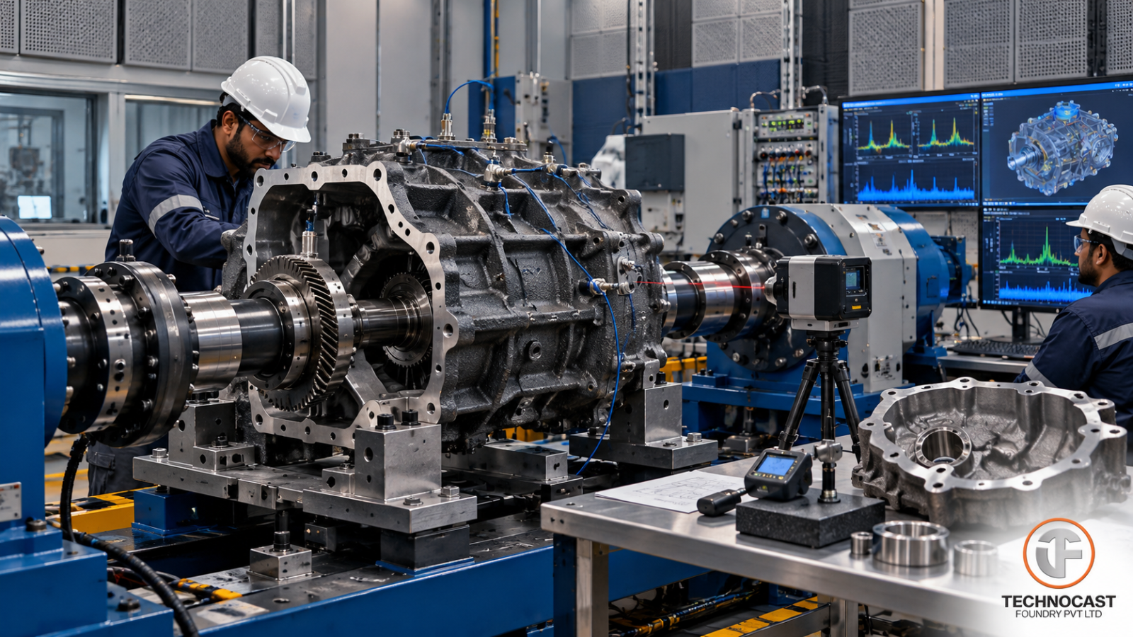
A gearbox or differential housing can pass visual inspection and still create expensive problems after assembly.
The most common failures are often not dramatic casting fractures.
They are problems such as:
- Bearing bores moving outside tolerance
- Input and output shafts losing alignment
- Gasket joints developing oil leaks
- Seal lands creating premature seal wear
- Thin walls amplifying gear-mesh vibration
- Machining stock disappearing from one side of a bore
- Porosity appearing after finish machining
For OEM engineers and sourcing teams, this means a gearbox housing should not be specified simply as:
“Cast this geometry in this material.”
The more useful engineering question is:
“Can the supplier repeatedly deliver the required stiffness, bearing alignment, sealing integrity and dimensional stability after casting and machining?”
That requires the complete manufacturing route to be considered:
Material → Casting design → Moulding → Solidification → Machining datums → GD&T → Leak verification → Final dimensional inspection
What Does a Gearbox Housing Actually Have to Do?
A transmission or differential housing performs several jobs simultaneously.
It must:
- Support bearings and shafts
- Maintain gear alignment
- Carry torque reactions
- Resist structural distortion
- Contain lubricant
- Provide mounting interfaces
- Manage vibration and noise
- Remain machinable at production scale
These requirements can conflict with each other.
Making every wall thicker may increase stiffness, but it also adds:
- Weight
- Material cost
- Solidification time
- Shrinkage risk
- Machining stock
Reducing wall thickness may save mass but create:
- Local flexibility
- Bearing-pocket distortion
- Higher vibration response
- Casting-fill challenges
The engineering objective is therefore not maximum mass or minimum mass.
It is controlled stiffness in the locations that influence drivetrain performance.
Material Selection for Gearbox and Differential Housings
The supplied research compares three broad material families:
- Grey cast iron
- Ductile iron
- Aluminium casting alloys
For Technocast, the most relevant discussion is the comparison between grey iron and ductile iron. Aluminium is useful as an engineering benchmark, but it should not be presented as a Technocast foundry capability unless independently confirmed.
EN-GJL-250 Grey Iron
EN-GJL-250 is commonly considered for gearbox and machinery housings because grey iron provides several useful characteristics.
These include:
- Vibration damping
- Machinability
- Dimensional stability
- Good stiffness
- Cost-efficient casting
The flake graphite structure helps damp mechanical vibration.
That can be particularly valuable around rotating machinery where gear-mesh excitation contributes to NVH.
The supplied research therefore identifies EN-GJL-250 as an attractive housing material where damping and dimensional stability are important.
The trade-off is lower ductility and impact resistance compared with ductile iron.
EN-GJS-500-7 Ductile Iron
Where higher structural strength and toughness are required, ductile iron may become more appropriate.
The source identifies EN-GJS-500-7 as having significantly higher tensile strength than EN-GJL-250 while maintaining similar density.
This can make it attractive for:
- Highly loaded differential housings
- Axle-related housings
- Heavy-duty transmission structures
- Components where local stress is higher
Ductile iron also requires tighter metallurgical control around:
- Magnesium treatment
- Inoculation
- Graphite morphology
- Nodularity
- Ferrite/pearlite balance
The choice between grey and ductile iron therefore depends on the actual failure mode.
Do Not Select Housing Material by Tensile Strength Alone
A gearbox housing is usually stiffness-driven before it becomes ultimate-strength-driven.
Consider what the housing actually needs to control:
- Bearing location
- Shaft alignment
- Gear contact
- Structural deflection
- Vibration
- Noise
A high tensile-strength material is not automatically the best answer.
Grey iron may outperform a stronger material in an application where damping dominates.
Ductile iron may be preferable where:
- Impact
- Fatigue
- Structural loading
- Thin high-stress sections
become more important.
Material selection must therefore consider:
Strength + stiffness + damping + geometry + fatigue + machinability + cost
rather than strength alone.
Housing Wall Thickness Should Begin With Castability
Design engineers often approach housing thickness from structural analysis first.
For cast components, manufacturability also needs to be considered early.
A wall must be capable of:
- Filling reliably
- Solidifying predictably
- Maintaining geometry
- Feeding thicker junctions
The supplied source provides practical wall-thickness guidance for different casting processes and also notes that shell moulding can support thinner sections than conventional heavier sand-casting routes in suitable geometries.
Those values should be treated as design starting points—not universal minimums.
Actual capability depends on:
- Material
- Casting size
- Flow length
- Moulding process
- Core design
- Tooling
- Foundry process capability
Why Uniform Wall Thickness Matters
Abrupt transitions from thin to very thick sections can create solidification problems.
Heavy nodes remain hot longer.
Potential results include:
- Shrinkage
- Porosity
- Residual stress
- Local microstructure variation
Where possible, the design should transition smoothly between sections.
Large masses should not be added simply because more material appears stronger.
Use Ribs for Stiffness Instead of Adding Mass Everywhere
Ribs allow engineers to place stiffness where the housing actually needs it.
Typical objectives include:
- Reducing panel flex
- Stabilising bearing pockets
- Strengthening bolt locations
- Increasing local bending stiffness
- Shifting vibration modes
The supplied research highlights the value of orienting ribs along load paths and using modal/FEA analysis rather than simply making every rib larger.
Bearing Pocket Ribbing
Consider a differential bearing pocket.
Instead of simply increasing the complete wall thickness, the housing may use:
- A ring around the bearing bore
- Radial ribs connecting the ring to bolt bosses
- A longitudinal spine along the axle centreline
The objective is to resist local ovalisation while controlling additional mass.
FEA can then be used to evaluate whether the ribs:
- Reduce displacement
- Improve bearing-pocket stiffness
- Shift local vibration modes
Gearbox NVH Starts With Housing Structure
Gear noise is not produced by gears alone.
The housing can amplify excitation generated within the drivetrain.
Gear-mesh forces can excite flexible housing panels.
Those panels may then radiate noise.
This means housing design influences:
- Gearbox noise
- Vibration
- Perceived machine quality
Useful design tools can therefore include:
- Static FEA
- Modal analysis
- Rib optimisation
A housing should be stiffened strategically so that its natural vibration behaviour does not unnecessarily amplify operating excitation.
Bearing Bores Are Among the Most Critical Housing Features
A gearbox can have excellent gears and bearings and still fail prematurely if their supporting bores are misaligned.
Important characteristics include:
- Diameter
- Roundness
- Cylindricity
- Position
- Coaxiality
- Perpendicularity
Bearing geometry directly influences shaft alignment.
Misalignment can contribute to:
- Edge loading
- Bearing wear
- Gear contact variation
- Noise
- Temperature rise
- Reduced life
The source explicitly recommends treating bearing-seat geometry and bore relationships as functional CTQs rather than general dimensions.
ISO Fits and Final Bore Requirements
Bearing fits may be specified using ISO 286 tolerance classes depending on the actual bearing arrangement and loading.
Examples may involve H7 or tighter/alternative classes depending on OEM design.
But the correct fit should come from the bearing and drivetrain design.
The casting supplier should not independently decide the final bearing fit.
The important foundry/manufacturing issue is ensuring there is enough:
- Casting stability
- Machining stock
- Datum control
to repeatedly machine the requested fit.
Control Position, Not Just Diameter
A perfectly sized bearing bore can still create a bad gearbox if it is in the wrong position.
For this reason, housing drawings should control functional relationships such as:
Input bearing bore ↔ Output bearing bore
Bearing axis ↔ Mounting face
Differential bore ↔ Opposite-side bearing bore
GD&T should be built around how the housing actually assembles.
Datum Strategy for Housing Castings
Datum planning should begin before machining fixtures are designed.
A practical housing strategy may include:
Datum A
A major machined mounting face.
Datum B
A primary functional bearing bore.
Datum C
A dowel, locating hole or other assembly feature.
The final scheme depends on product architecture.
The important principle is that:
design datums + machining datums + inspection datums
should support the same functional intent.
Split Housings Need Additional Control
Gearbox cases frequently use:
- Main housing
- Cover
- Split case halves
Where bearing geometry crosses a split, assembly location becomes critical.
Dowel features and locating surfaces need to provide repeatable positioning.
Otherwise two individually acceptable pieces may create bore mismatch when assembled.
Machining Allowance Is an Engineering Parameter
Machining stock should not be treated as:
“Add a few millimetres everywhere.”
It must cover:
- As-cast dimensional variation
- Distortion
- Part location uncertainty
- Surface cleanup
- Post-treatment movement
while avoiding unnecessary material.
The source notes that shell-moulded components can often operate with tighter stock allowances than heavier no-bake castings, while large sand-cast housings generally require more allowance on critical surfaces.
Exact allowances need to be agreed with the selected foundry.
Keep Stock Removal Balanced
Heavy asymmetric machining can release residual stress unevenly.
This can cause:
- Flatness movement
- Bore shift
- Housing distortion
Where significant material needs to be removed, the manufacturing sequence should consider:
Rough machining → Stability / stress-relief strategy where required → Finish machining
rather than removing all material in one final operation.
Grey Iron Stress Relief
The source notes stress-relief treatment as one recognised method for reducing machining-distortion risk in appropriate grey-iron castings.
The actual thermal cycle should be developed according to:
- Material
- Housing geometry
- Casting condition
- Customer specification
rather than using one universal temperature/time recipe.
Gasket Rail Flatness Matters
Gearbox housing sealing does not depend only on gasket quality.
The joint must also maintain appropriate geometry.
Potential problems include:
- Waviness
- Local machining variation
- Distortion
- Bolt-pattern interaction
These can create uneven clamp load.
The drawing should therefore specify suitable controls for gasket rails and mounting faces.
Shaft Seal Counter-Faces
Radial shaft seals operate directly against a rotating surface.
The relevant surface needs controlled:
- Roughness
- Lay
- Runout
- Geometry
The supplied research provides typical surface-finish and runout guidance for radial seal lands while correctly noting that the final requirement depends on the seal design and diameter.
OEM engineers should therefore use the actual seal supplier requirement rather than copying a generic Ra value onto every drawing.
Why Spiral Machining Marks Can Matter
Some seal interfaces are sensitive not just to average roughness but also to machining lay.
A spiral tool mark may effectively act as a microscopic pump path.
That can move lubricant along the shaft surface and contribute to leakage.
Surface specification should therefore reflect:
- Roughness
- Lay
- Manufacturing process
where the seal application requires it.
Leak Testing of Gearbox and Differential Housings
Some housing designs contain:
- Oil cavities
- Cast galleries
- Plugged passages
- Sealed interfaces
For such components, leak testing may be part of final validation.
Potential methods include:
- Air pressure decay
- Other controlled leak-test systems
- More sensitive methods for specialised applications
The correct method depends on:
- Component architecture
- Acceptable leak rate
- Production volume
- Customer requirements
The source emphasises that leak testing should define test medium, pressure, stabilisation and a measurable acceptance criterion rather than merely stating “leak test required.”
Leak-Test Measurement Needs Its Own Capability Study
A test station is itself a measurement system.
If pressure decay is used, results can be influenced by:
- Fixture sealing
- Temperature
- Test volume
- Stabilisation time
- Plug condition
A production test therefore needs repeatability.
Where required by the quality plan, MSA or equivalent validation should confirm that test-system variation is sufficiently small relative to the acceptance limit.
Shell Moulding vs No-Bake for Housing Castings
Process selection should follow:
- Component size
- Wall thickness
- Geometry
- Production volume
- Surface finish
- Dimensional requirement
Shell Moulding
Shell moulding can offer:
- Better dimensional repeatability
- Improved surface quality
- Relatively thinner cast sections
- Lower machining stock
for suitable parts.
It may therefore be attractive for precision housings where part geometry and production economics fit the process.
No-Bake Moulding
No-bake moulding offers more flexibility for:
- Larger housings
- Heavy sections
- Large core packages
- Lower-volume industrial programs
The trade-off is that larger sand castings may require:
- More machining stock
- Greater attention to distortion
- Stronger process control
The supplied source makes this same process distinction and also discusses hybrid use of precision cores with larger external moulding routes.
Quality Assurance for Gearbox Housings
Inspection should be aligned to component risk.
Chemistry and Metallurgy
For grey iron, verify the required grade and microstructure.
For ductile iron, relevant controls may include:
- Chemistry
- Nodularity
- Matrix
- Mechanical properties
according to specification.
Dimensional Verification
Housing programs may require objective measurement of:
- Bearing bores
- Bore position
- Mounting faces
- Dowel locations
- Gasket rails
- Critical GD&T
CMM can be especially valuable for evaluating relationships between multiple functional features.
Magnetic Particle Testing
For suitable ferrous components, MT/MPI may be used to detect surface and near-surface indications in critical areas such as:
- Fillets
- Bosses
- Bearing pockets
where the customer specification requires it.
Penetrant Testing
PT is generally more relevant to non-magnetic materials or specific surface inspection needs.
It should not be added indiscriminately to ferrous housing specifications if another method better addresses the actual risk.
Radiography
Radiography may be specified where internal integrity in critical regions needs to be demonstrated and the component/specification justifies it.
However, RT should not be assumed to be a Technocast in-house capability unless confirmed through current company documentation.
Supplier Qualification for Transmission Housing Castings
A supplier audit should examine the complete manufacturing route.
Engineering
Can the foundry provide DFM input on:
- Walls
- Ribs
- Fillets
- Gating
- Feeding
- Machining stock?
Metallurgy
Can the supplier demonstrate:
- Chemistry control
- Inoculation
- Ductile-iron treatment where applicable
- Traceability?
Tooling
How are:
- Patterns
- Core boxes
- Wear
- Engineering revisions
controlled?
Machining
Can the supplier hold the required:
- Bearing bores
- Datum relationships
- Flatness
- Positions?
Metrology
Can the supplier provide reliable dimensional reports for the functional geometry?
Quality System
Does the supplier demonstrate:
- Non-conformance control
- Calibration
- Traceability
- Corrective action
- Change control?
Where automotive-style PPAP is required, confirm the supplier’s actual ability to provide:
- PFMEA
- Control Plan
- MSA
- Capability studies
- Dimensional reports
- Material results
rather than assuming those systems from certification alone.
Process Capability for Critical Bores
Final inspection tells you whether the measured component passed.
Process capability tells you whether the manufacturing system is stable enough to continue producing acceptable components.
For high-volume housings, OEM teams may therefore monitor Cp/Cpk or another agreed process-capability method for critical:
- Bearing diameters
- Bore positions
- Face dimensions
where appropriate.
Technocast Foundry for Gearbox and Differential Housing Programs
For gearbox and differential housing sourcing, the supplier needs to manage several disciplines together:
Metallurgy + Casting geometry + Machining + Dimensional inspection
Technocast’s documented ferrous capabilities relevant to this type of program include:
- Grey iron
- Ductile iron
- Shell moulding
- No-bake moulding
- CNC machining
- CMM inspection
- Spectrometry
- Heat treatment
- Relevant NDT such as UT where applicable
For a specific gearbox or differential housing, the manufacturing route should be selected according to:
- Material
- Housing dimensions
- Section thickness
- Annual volume
- Required bore geometry
- Machining content
- Inspection requirement
Do not assume that every transmission housing should use the same moulding route.
Similarly, leak-test capability should be confirmed for the actual project rather than assumed as a standard Technocast capability.
Gearbox Housing RFQ Checklist
Provide the foundry with:
Component Drawing
Latest controlled revision.
3D Model
Where available.
Material Grade
For example:
- EN-GJL-250
- EN-GJS-500-7
or the exact customer specification.
Annual Volume
Including peak production requirements.
Critical Bearing Features
Identify:
- Fits
- Diameter tolerances
- Bore positions
- Coaxiality
- Perpendicularity
Datum Scheme
Clearly identify functional datums.
Machining Stock
Agree stock according to the selected casting process.
Sealing Requirements
Define:
- Gasket face
- Shaft-seal land
- Surface finish
- Runout
where applicable.
Leak-Test Requirement
Where required, specify:
- Method
- Pressure
- Stabilisation
- Acceptance
NDT
Define only the methods and zones actually required.
Quality Documentation
Specify:
- Dimensional report
- Material certificate
- Microstructure requirements
- Traceability
- PPAP/FAI package where applicable
Conclusion
A gearbox or differential housing is not just a container around gears.
It controls:
Bearing alignment
Shaft position
Structural stiffness
Noise and vibration behaviour
Lubricant sealing
Assembly geometry
That means the casting specification needs to connect structural design with foundry capability and precision machining.
The strongest housing programs therefore align:
Material → Walls and ribs → Solidification → Datum strategy → Machining → GD&T → Sealing → Inspection
before tooling is released.
For OEM engineers, the key supplier question should not simply be:
“Can you cast this housing?”
Ask:
“Can you repeatedly maintain the bearing geometry, structural stiffness and sealing interfaces after casting and machining?”
That is the difference between supplying a casting and supplying a production-ready transmission housing.
Request a Gearbox or Differential Housing Review
For a new or re-sourced housing, send Technocast:
- Drawing
- 3D model
- Material grade
- Single-piece weight
- Annual volume
- Critical bearing dimensions
- Machining requirements
- Sealing/leak requirements
- Inspection requirements
The component can then be reviewed for moulding route, DFM, machining, tolerance strategy and quality requirements before tooling release.
Frequently Asked Questions
Which is better for gearbox housings: grey iron or ductile iron?
It depends on the application. Grey iron provides strong damping and machinability, while ductile iron provides higher strength and better ductility. The correct choice depends on stiffness, NVH, fatigue, impact and geometry.
Why is grey iron commonly used for gearbox housings?
Its graphite structure gives it good vibration damping, dimensional stability and machinability, which can be useful around rotating machinery.
Why are bearing bore positions so important?
Bearing bores establish shaft and gear alignment. Positional or coaxiality errors can increase bearing load, gear noise and premature wear.
Should gearbox housing ribs simply be made thicker?
Not necessarily. Rib location and height can improve stiffness more efficiently than adding mass everywhere. Rib design should follow load paths and, where appropriate, FEA/modal analysis.
What is the advantage of shell moulding for housings?
For suitable components, shell moulding can provide improved dimensional repeatability, surface finish and thinner sections, potentially reducing machining stock.
When is no-bake moulding suitable?
No-bake is often useful for larger housings, heavy sections, complex core packages and lower-volume production where flexibility is valuable.
Does every gearbox housing require leak testing?
No. Leak testing should be specified when the housing design contains oil cavities, galleries, plugged passages or other features where pressure/leak integrity is functionally important.
What should I send for a gearbox housing RFQ?
Provide the drawing, material grade, weight, annual quantity, critical bore requirements, datum strategy, machining details, sealing requirements and inspection plan.
Related at Technocast: Transmission and powertrain castings · Automotive castings
Read next: Casting and machining from one supplier · Sand casting tolerances and machining allowances