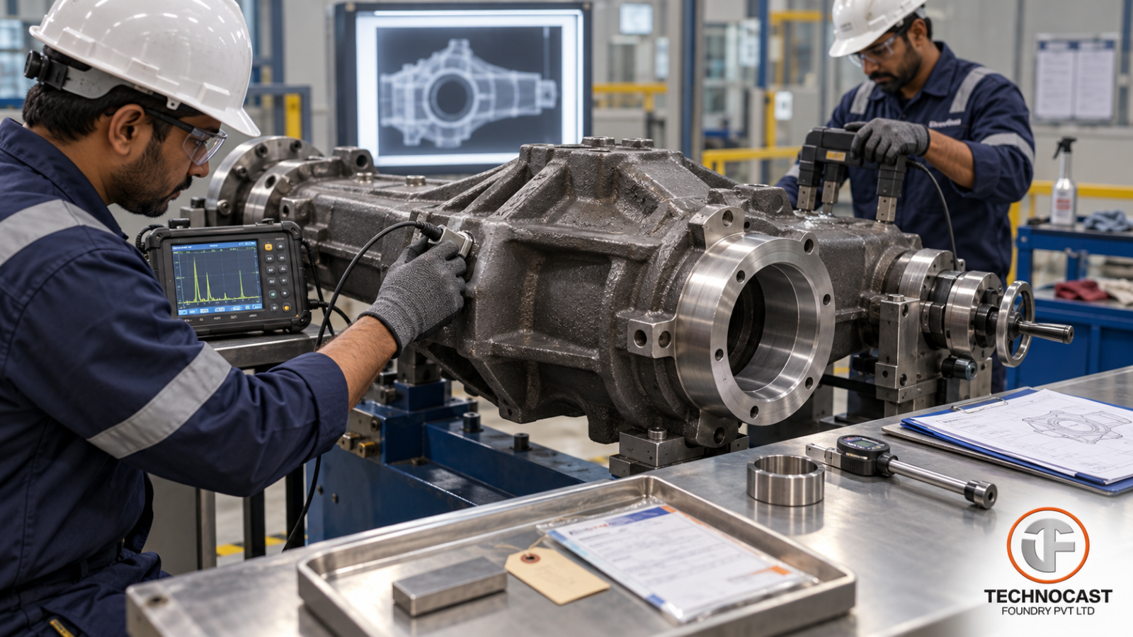
A critical casting should not be considered acceptable simply because:
“NDT was done.”
The more important questions are:
Which failure risk was inspected?
Was the correct method used?
Was the component inspected at the correct manufacturing stage?
Which areas were actually covered?
What acceptance criteria were applied?
For OEM engineers, supplier-quality teams and procurement managers, NDT should be selected around the component’s actual risk—not around whichever inspection equipment happens to be available.
At Technocast Foundry Pvt. Ltd., our approach is based on one broader manufacturing principle:
One stop solution, from casting to ready-to-fit parts.
That means inspection should remain connected to metallurgy, casting geometry, machining and the finished component condition.
A casting that passes an internal-soundness examination can still fail dimensional inspection.
A dimensionally perfect component can still contain an unacceptable internal discontinuity.
A pressure-tight component can still have the wrong material chemistry.
Each quality method answers a different engineering question.
Zero Defect Is an Objective, Not an Inspection Claim
The term zero defect should be used carefully.
No inspection method proves absolute freedom from every possible discontinuity throughout every location of a complex casting.
A better engineering approach is:
Prevent defects → Identify critical risks → Select the right verification method → Define measurable acceptance criteria → Use results to improve the process
Inspection is evidence.
It is not a substitute for:
- Process control
- Casting DFM
- Metallurgy control
- Feeding design
- Core control
- Machining discipline
The goal should be zero-defect manufacturing performance while maintaining realistic, measurable acceptance requirements.
Start With the Failure Risk
Before specifying UT, MPI, RT or PT, identify what failure you are trying to prevent.
For example:
Internal shrinkage near a heavy bearing boss
This is primarily an internal soundness concern.
Surface crack around a highly stressed fillet
This is primarily a surface or near-surface concern.
Bearing bore positioned incorrectly
This is a dimensional/geometrical concern.
Incorrect alloy chemistry
This is a material-verification concern.
Pressure leakage through an interconnected path
This is a functional tightness concern.
Different questions require different evidence.
Casting Inspection Methods at a Glance
| Method | Primary Question |
|---|---|
| Ultrasonic Testing – UT | Are specified internal zones showing relevant ultrasonic indications? |
| Magnetic Particle Inspection – MPI/MT | Are relevant surface or near-surface discontinuities present? |
| Radiography – RT/X-ray | Are specified volumetric discontinuities visible in the examined views? |
| Dye Penetrant Testing – PT | Are surface-opening discontinuities present? |
| Pressure/Hydrostatic Testing | Does the defined pressure boundary meet the required functional test? |
| CMM Inspection | Does the component meet dimensional and geometrical requirements? |
| Spectrometry | Does the material chemistry comply with the specified grade? |
The important point is simple:
These methods are complementary—not interchangeable.
Ultrasonic Testing: Looking Into the Casting
Ultrasonic testing uses sound energy to examine suitable internal regions.
For appropriate castings, UT may help detect indications associated with conditions such as:
- Internal cracks
- Shrinkage-related discontinuities
- Certain inclusions
- Loss of expected back-wall response
depending on the material, geometry, procedure and calibration.
Where UT Can Be Valuable
UT may be useful around:
- Heavy sections
- Bearing supports
- Structural load paths
- Critical steel casting sections
- Selected ductile-iron regions
where the inspection technique has been validated.
UT Is Not Automatically Transferable Between Materials
This is especially important.
A technique that performs well on steel should not automatically be assumed to behave identically on:
- Ductile iron
- Grey iron
Graphite structure and material attenuation can influence ultrasonic response.
For cast iron, inspectability should therefore be demonstrated for the:
- Material
- Section thickness
- Geometry
- Probe
- Calibration approach
being proposed.
What Should a UT Specification Define?
Do not simply write:
“100% UT required.”
Define:
- Inspection zones
- Technique
- Reference sensitivity
- Calibration approach
- Coverage
- Relevant indication criteria
- Acceptance standard
where required by the application.
The phrase “100% UT” can be misleading if some areas are physically inaccessible or technically unsuitable.
UT Cannot Tell You Everything
An ultrasonic indication may demonstrate that a reflector exists.
It does not automatically prove its root cause.
Engineering investigation may still be required to determine whether the underlying mechanism is:
- Shrinkage
- Crack
- Inclusion
- Geometry
or another condition.
Inspection identifies evidence.
Root-cause analysis explains why the evidence exists.
Magnetic Particle Inspection: Surface and Near-Surface Discontinuities
Magnetic particle inspection is applicable to suitable ferromagnetic materials.
It can be effective for identifying relevant:
- Surface cracks
- Near-surface cracks
- Hot tears
- Certain grinding or repair-related cracking
depending on the procedure.
Potential critical regions include:
- Fillets
- Boss transitions
- Highly loaded surfaces
- Repair locations
- Machined areas
where the drawing or quality plan requires examination.
MPI Requires Controlled Magnetisation
The inspection technique needs to consider the likely orientation of discontinuities.
A crack may be easier to detect when the magnetic field crosses it appropriately.
That means the inspection plan may need:
- More than one magnetisation direction
- Defined current/field approach
- Controlled inspection coverage
depending on geometry.
Surface Condition Affects MPI
Casting surface condition can influence inspection interpretation.
Rough surfaces may collect magnetic particles differently from smoother surfaces.
That can make it harder to distinguish relevant indications from background noise.
Inspection planning should therefore account for:
- As-cast surface
- Blasted surface
- Ground surface
- Machined surface
rather than assuming identical sensitivity on every condition.
MPI Does Not Inspect Austenitic Stainless Steel
Magnetic particle inspection relies on suitable ferromagnetic material behaviour.
It is therefore not the correct method for austenitic stainless materials such as many CF8/CF8M-type castings.
A different surface-inspection method may be required.
Dye Penetrant Testing: Surface-Opening Discontinuities
PT is useful for identifying discontinuities that are open to the inspected surface.
It can be applied to a broader range of suitable materials than MPI because it does not depend on ferromagnetism.
Potential uses include:
- Machined sealing surfaces
- Stainless components
- Repair zones
- Other accessible surfaces
where surface-breaking cracks are a concern.
Surface Preparation Is Critical for PT
PT effectiveness depends strongly on preparation.
The surface needs to be appropriately:
- Clean
- Accessible
- Free from contamination that interferes with penetration
The procedure should define cleaning and examination requirements.
PT Is Not an Internal Porosity Test
This distinction matters.
PT can identify indications connected to the surface.
It cannot be used to claim:
“No internal porosity exists.”
If internal volumetric soundness is the concern, another inspection method is required.
Radiography: Volumetric Examination
Radiographic testing uses penetrating radiation to produce an image of internal casting conditions.
It may help identify conditions such as:
- Gas porosity
- Shrinkage
- Certain inclusions
- Other volumetric discontinuities
when the geometry, thickness and technique make them visible.
RT Can Be Valuable for Critical Zones
Potential applications include:
- Pressure walls
- Heavy section transitions
- First-article validation
- Areas where internal shrinkage risk is significant
But the inspection plan should specify the actual zones.
A statement such as:
“X-ray tested”
does not explain:
- Which views were taken
- Which areas were covered
- Which severity criteria were used
Radiography Is Not Automatically Complete Volumetric Assurance
Casting geometry can create overlapping material in the image.
Thickness influences sensitivity.
The selected view influences what can be detected.
Therefore define:
- Required views
- Coverage
- Image-quality requirements
- Reference criteria
- Acceptance severity
rather than treating one radiograph as proof of the entire casting.
Acceptance Criteria Must Be Agreed
A discontinuity visible in RT does not automatically mean the component must be rejected.
The engineering question is:
What type, extent and location are acceptable for this specific application?
Critical areas may require different limits from noncritical areas.
This is why zone-based acceptance is usually more useful than broad statements such as:
“No porosity allowed anywhere.”
Pressure and Hydrostatic Testing: Functional Integrity
Pressure testing answers another question:
Does the specified pressure boundary perform under the defined test condition?
This can be important for components such as:
- Valve bodies
- Pump casings
- Hydraulic housings
where applicable.
Pressure Testing Is Not the Same as NDT Soundness Examination
A casting can pass a pressure test and still contain internal discontinuities that do not create a connected leak path.
Similarly, a casting can have acceptable internal structure but fail a pressure test because of:
- Machining issue
- Seal condition
- Plug interface
- Assembly problem
Therefore:
Internal soundness
and:
Functional tightness
should remain separate acceptance decisions.
Define the Purpose of the Pressure Test
Do not write only:
“Pressure test required.”
Define where applicable:
- Test medium
- Test pressure
- Hold duration
- Test stage
- Allowable leakage
- Relevant deformation requirement
- Governing specification
Do not apply one generic pressure multiplier to unrelated components.
CMM: Dimensional and Geometrical Verification
CMM inspection is not an NDT method in the same sense as UT or MPI, but it is essential in the critical-casting quality system.
It answers:
Is the component geometrically correct?
CMM can support inspection of:
- Bore position
- Hole pattern
- Profiles
- Flatness
- Perpendicularity
- Datum relationships
- Other GD&T requirements
CMM Should Follow Functional Datums
Consider a gearbox housing.
The critical issue may not be the diameter of one bearing bore alone.
It may be the relationship between:
Bearing bore A → Bearing bore B → Mounting face
The inspection strategy should therefore follow the drawing’s functional datum structure.
CMM Cannot Detect Internal Casting Soundness
A component can have excellent CMM results and still contain an internal defect.
Likewise, a casting can be internally sound but dimensionally incorrect.
This is why:
Dimensional acceptance
and:
Soundness acceptance
must remain separate.
Spectrometry: Verifying Material Chemistry
Spectrometry addresses another fundamental risk:
Did we produce the specified material?
For ferrous casting programs, chemistry control may include elements relevant to the specified material grade.
This helps prevent:
- Material mismatch
- Chemistry drift
- Incorrect alloy condition
depending on the specification.
Chemistry Is Not Mechanical Performance
A chemistry result does not by itself prove every required mechanical property.
Depending on the material and customer specification, additional evidence may involve:
- Tensile testing
- Hardness
- Metallography
- Nodularity
- Other specified material controls
The quality plan should identify which evidence is actually required.
Keep Four Acceptance Decisions Separate
For critical castings, it is useful to think about four broad quality decisions:
1. Material
Is the chemistry/material condition correct?
2. Soundness
Are relevant internal or surface discontinuities within agreed limits?
3. Geometry
Does the component meet dimensional and GD&T requirements?
4. Functional Performance
Does the component satisfy defined functional tests such as pressure integrity where required?
A pass in one category does not automatically create a pass in the others.
Inspection Should Follow the Manufacturing Route
The timing of inspection can matter almost as much as the inspection method.
A useful inspection sequence may include several stages.
Before Pouring
Define:
- Material grade
- Chemistry window
- Sampling
- Identification
After Casting and Cleaning
Visual inspection and other applicable examination may identify problems before additional value is added.
After Heat Treatment
Where required, certain examinations should be performed in the condition defined by the specification.
Before Extensive Machining
For expensive components, screening critical internal regions early can prevent unnecessary machining value being added to a reject.
During and After Machining
Machining creates new functional surfaces.
It can also expose previously hidden:
- Cavities
- Pinholes
- Other discontinuities
The inspection plan should define how these newly exposed conditions are handled.
Before Final Release
Complete the required:
- Dimensional checks
- Applicable NDT
- Functional testing
- Documentation review
before shipment.
Machining Can Change the Inspection Requirement
Imagine a raw housing with a heavy bearing boss.
The raw surface may be acceptable.
After boring, however, machining removes several millimetres of material and exposes a previously subsurface indication.
The relevant question is then:
Is the finished machined surface acceptable?
This is why inspection planning must consider the final manufacturing condition—not only the raw casting.
What Happens When Machining Exposes a Cavity?
The decision process should already exist before production begins.
A good response includes:
- Stop and contain affected parts.
- Preserve heat/lot traceability.
- Map the indication location.
- Compare with casting geometry.
- Review machining stock and datum.
- Perform additional inspection where required.
- Obtain authorised engineering disposition.
Do not automatically assume:
“Casting porosity.”
The root cause may involve:
- Core position
- Casting variation
- Machining location
- Internal shrinkage
- Another mechanism
Do Not Default to Every Test on Every Casting
Maximum inspection is not automatically good engineering.
Testing every component with every available method can add:
- Cost
- Lead time
- False interpretation risk
without necessarily improving safety.
Inspection scope should follow:
- Component criticality
- Failure mode
- Material
- Geometry
- Process capability
- Customer/OEM requirement
The design authority should determine which evidence is necessary.
Automotive and Off-Highway Castings
For components such as:
- Steering knuckles
- Differential housings
- Axle components
- Transmission housings
consider how inspection connects with:
- Fatigue-critical transitions
- Bearing locations
- Structural bosses
- Special characteristics
Prototype, approval and serial-production inspection may not use identical sampling.
Wind-Energy Castings
For heavy wind-energy components, inspectability can vary across large section thicknesses.
Potential critical areas can include:
- Highly loaded transitions
- Bearing-support regions
- Bolt interfaces
- Heavy sections
The inspection plan should identify zones rather than simply writing:
“NDT required.”
Pump, Valve and Hydraulic Castings
These applications may need separate controls for:
- Casting soundness
- Machined sealing geometry
- Pressure boundary
- Final leakage
Do not assume one hydrostatic test replaces all other inspection.
Inspection Reports Must Be Auditable
A report containing only:
PASS
does not tell the customer much.
Depending on program requirements, inspection documentation should identify:
- Component/lot
- Drawing revision
- Procedure
- Examined areas
- Equipment identification
- Calibration status
- Operator qualification where required
- Actual findings/results
- Acceptance basis
- Disposition
This becomes particularly important for safety- and quality-critical components.
Nonconforming Castings Need Controlled Disposition
When an indication exceeds acceptance criteria, the next decision should not be made informally by an operator.
Potential disposition may include:
- Reject
- Rework
- Repair
- Concession/deviation
depending on customer requirements.
For critical components, repair should follow an approved procedure.
Where required, obtain written customer approval.
Inspection Results Should Improve the Manufacturing Process
NDT is most valuable when the results feed back into process improvement.
For example:
Repeated internal indications in one heavy section should trigger investigation of:
- Feeding
- Solidification
- Geometry
- Moulding process
Repeated surface cracking may trigger review of:
- Section transitions
- Cooling
- Handling
- Grinding
- Heat treatment
The long-term solution should not be:
“Inspect harder.”
It should be:
“Understand and reduce the mechanism creating the indication.”
One Stop Solution, From Casting to Ready-to-Fit Parts
At Technocast Foundry Pvt. Ltd., our broader manufacturing approach is:
One stop solution, from casting to ready-to-fit parts.
For suitable programs, the quality discussion can connect:
Material control → Casting → Heat treatment → CNC machining → Dimensional inspection → Applicable NDT → Finished component
instead of treating quality as an independent final operation.
Technocast’s established relevant capabilities include:
- Grey iron
- Ductile iron
- Carbon steel
- Alloy steel
- Spectrometry
- CMM dimensional inspection
- Ultrasonic testing
- CNC machining
- Heat treatment where applicable
For other methods such as:
- MPI
- PT
- Radiography
- Pressure testing
- Specialist functional testing
the exact availability and whether the process is internal or partner-supported should be confirmed for the specific RFQ before making a contractual capability statement.
Build the Inspection Plan Before Production
For a new critical casting, send:
- Drawing
- Material specification
- Component weight
- Annual quantity
- Service conditions
- Critical zones
- Machining scope
- Applicable OEM specification
- Inspection requirements
- Acceptance criteria
Then agree:
What needs to be inspected?
Which method answers that question?
When should the inspection happen?
What constitutes acceptance?
Who has authority when the result is nonconforming?
Conclusion
The strongest critical-casting quality plan does not ask:
“How many inspection methods can we apply?”
It asks:
“What can fail, and what evidence proves that risk is controlled?”
UT, MPI, RT, PT, CMM, spectrometry and pressure testing all provide different information.
The right strategy connects:
Failure risk → Inspection method → Critical zone → Manufacturing stage → Acceptance criteria → Corrective action
That is how inspection supports a zero-defect objective.
Not by claiming that one test can prove a casting is perfect.
But by applying the right controls throughout the route from:
Casting to ready-to-fit parts.
Frequently Asked Questions
Which NDT method is best for casting porosity?
There is no single answer. Radiography may be useful for certain volumetric porosity, while UT may be appropriate for selected internal regions depending on material, geometry and the qualified technique.
Can ultrasonic testing be used on ductile iron?
It can be used in suitable applications, but the inspection technique should be validated for the material, section thickness, geometry and required coverage.
Can MPI detect internal casting defects?
MPI is primarily used for relevant surface and near-surface discontinuities in suitable ferromagnetic materials. It is not a general volumetric internal-inspection method.
What is the difference between PT and MPI?
PT detects discontinuities open to the surface and can be used on suitable non-magnetic materials. MPI is used on ferromagnetic materials for relevant surface and near-surface indications.
Does hydrostatic testing prove a casting has no porosity?
No. It demonstrates performance under the defined pressure-test conditions. Internal discontinuities that do not create a connected leakage path may still exist.
Can CMM replace NDT?
No. CMM verifies geometry and dimensions. NDT addresses specified material discontinuities.
Should every critical casting receive every NDT method?
No. Inspection should be selected based on failure risk, material, component geometry, process capability and customer requirements.
When should casting inspection happen?
The inspection plan may include stages after casting, after heat treatment, before machining, after machining and before final release depending on component risk.